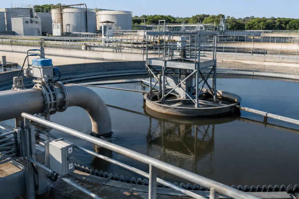
Plant expansions and tightening municipal discharge permits force facility managers to re-evaluate how they handle high-solids effluent streams. Selecting a clarifier for industrial wastewater requires balancing heavy hydraulic surges, variable suspended solids, and tight real estate constraints.
The right clarifier choice depends on how wastewater chemistry, sludge behavior, and available layout interact.
The Role of Clarifiers in Industrial Treatment Trains
Clarifiers rely on gravitational sedimentation to remove heavy particulates, flocculated solids, and chemical precipitates from raw process water. They lower the solids load on downstream filtration systems, membranes, and biological stages.
Core Mechanics: Coagulation, Flocculation, and Settling
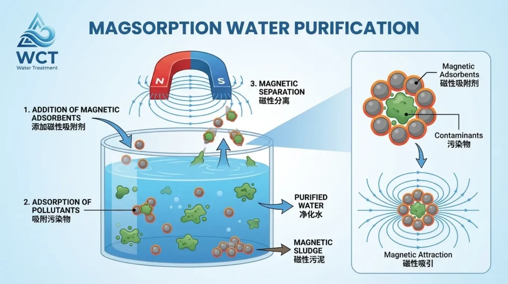
Fine suspended solids carry negative surface charges that prevent natural agglomeration.
- Charge neutralization: Coagulant dosing collapses the repulsive barrier in rapid mix.
- Floc bridging: Polymer addition links micro-flocs into heavier agglomerates in slow mix.
- Gravity separation: Quiescent settling lets particles drop while clarified water overflows weirs.
Where Clarifiers Fit in the Process Train
Industrial facilities deploy clarifiers at multiple process nodes depending on primary treatment goals. Primary clarifiers knock down bulk total suspended solids (TSS) and insoluble heavy metals before secondary biological basins or advanced oxidation.
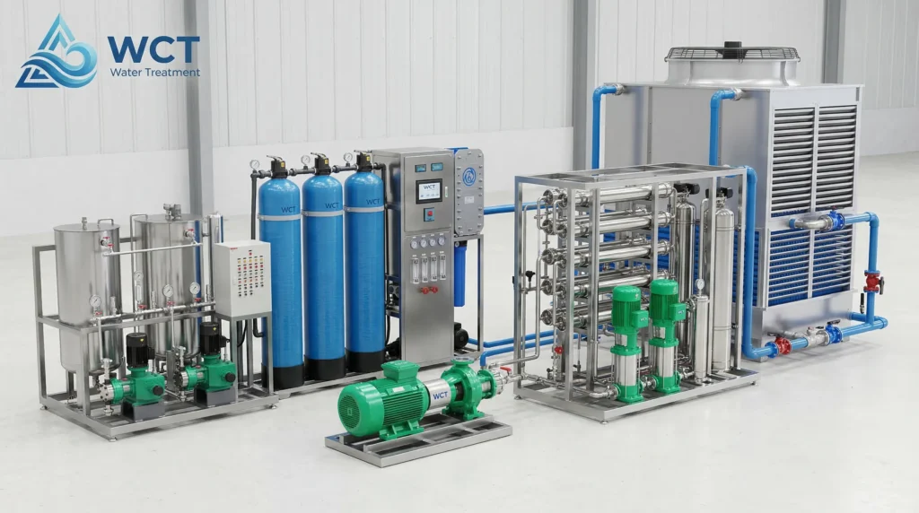
In tertiary stages, clarifiers capture chemical precipitates and polishing flocs. Placing a primary settling unit before tertiary Wct Industrial Sand Filters For Wastewater Treatment prevents premature media blinding. This layout also reflects proven best practices for industrial water system design.
Core Types of Industrial Clarifiers Compared
Selecting between circular sedimentation tanks, inclined plate separators, and peripheral feed basins depends on site footprint, flow dynamics, and target particle settling speeds.
Circular Clarifiers (Center Feed)
Center-feed circular clarifiers introduce raw influent through a central feedwell baffle. The center well dissipates influent velocity and promotes uniform radial flow toward perimeter overflow weirs.
These units provide substantial liquid volume and sludge storage. They handle high TSS fluctuations well but require a large land footprint, making them common in greenfield plants.
Incline Plate (Lamella) Clarifiers
Inclined plate clarifiers use a series of parallel inclined plates sloped at 55 to 60 degrees. This geometry increases effective settling surface area up to ten times compared to open basins with identical footprints.
Gravity draws solids down the steep plate channels into a lower sludge hopper while clean water flows upward. They fit well in compact indoor installations, skid systems, and plant retrofits.
Peripheral Feed Clarifiers (e.g., Spiraflo)
Peripheral feed systems introduce water along the outer tank wall rather than through the center. Flow travels downward along a circular baffle before moving inward toward central collection troughs.
This raceway design eliminates hydraulic short-circuiting and optimizes basin volume. It allows higher loading rates while maintaining low effluent turbidity in process facilities.
| Clarifier Type | Footprint Required | Surface Overflow Rate | Best Industrial Fit |
|---|---|---|---|
| Circular Center-Feed | Large open basin footprint | 0.2 – 0.6 gpm/ft2 | High-flow plants, primary heavy solids, bulk sludge storage |
| Incline Plate (Lamella) | Compact (up to 80% reduction) | 0.2 – 0.5 gpm/ft2 (effective) | Tight indoor spaces, metal finishing skids, plant retrofits |
| Peripheral Feed | Moderate circular footprint | 0.4 – 0.8 gpm/ft2 | Variable hydraulic loads, fine light flocs, secondary clarification |
Evaluating target surface overflow rates helps engineers determine whether a compact lamella or a conventional circular basin fits plant capacity. Reviewing specific hydraulic loading rate clarifier design limits prevents hydraulic short-circuiting during peak flow events.
Sludge Removal Mechanism Designs
Sludge accumulation control determines whether a clarifier operates continuously or suffers from rake binding, anaerobic bed souring, and solids carryover into clean discharge streams.
Scraper Mechanisms
Scraper arms feature angled flight blades mounted to a rotating central shaft. As the rake rotates slowly, the blades plow settled sludge along the tank floor toward a center discharge hopper.
Scrapers handle heavy, dense mineral sludges well. They require high-torque drive units and mechanical overload switches to protect the assembly when handling heavy lime or ore tailings.
Spiral Scrapers
Spiral scrapers feature continuous curved blades that extend from the outer wall to the center sump. The spiral geometry moves settled solids inward continuously rather than in intermittent pushes.
This continuous motion reduces sludge retention time on the tank floor. It prevents biological gas flotation and works well in secondary activated sludge and primary food processing streams.
Suction Headers (Tow-Bro Style)
Suction header mechanisms use submerged manifold pipes fitted with suction nozzles. Differential head or a dedicated pump draws sludge directly through the nozzles along the entire tank radius.
This rapid removal cleans the floor without disturbing delicate biological flocs. It is ideal for light biomass that breaks apart under mechanical scraper blade pressure.
- Verify solids specific gravity: Heavy metals require high-torque scrapers; delicate biological solids need suction or spiral collection.
- Check drive torque ratings: Ensure automatic rake-lift assemblies are specified for high TSS applications.
- Evaluate hopper slope angles: Standard floors slope at 1:12, while sticky chemical sludges require 1:4 or steeper cone hoppers.
- Confirm discharge pumping schedules: Intermittent pump-out must be timed to prevent sludge compaction in bottom sumps.
Matching Clarifier Technology to Industrial Applications
Effluent composition dictates basin geometry, chemical dosing, and material selection. Installing a standard wastewater clarifier without accounting for specific chemistry leads to operational failure.
Mining and Primary Metals
Mining runoff and metal plating effluents contain high concentrations of heavy metal hydroxides and abrasive mineral fines. These streams require pH neutralization, coagulants, and heavy solids removal.
Clarifiers in this sector need high-torque drives, abrasion-resistant coatings, and steep bottom hoppers. Lamella plate units with stainless steel plates handle metal hydroxide precipitation efficiently in tight spaces.
Chemical Processing and Manufacturing
Chemical process wastewater features wide pH swings, corrosive solvents, and varied organic loads. Equipment must withstand chemical attack while breaking emulsified contaminants.
Coagulation tanks require rapid mixing, followed by pH adjustment and polymer addition. Installing corrosion-resistant fiberglass or coated carbon steel ensures long service life for water treatment equipment for industrial use in aggressive chemical applications.
Food & Beverage Production
Food processing plants generate wastewater high in biological oxygen demand (BOD), fats, oils, and grease (FOG), and organic solids. FOG carryover rapidly blinds settling plates if unmanaged.
Primary clarification requires integrated surface skimming blades and scum baffles to remove floating grease. Spiral scrapers then remove sticky organic solids before secondary treatment stages.
| Industrial Sector | Major Contaminant | Recommended Pre-Treatment | Clarifier Configuration |
|---|---|---|---|
| Mining & Mineral Processing | Heavy metals, TSS, gypsum scale | pH elevation, coagulant dosing | Heavy-torque circular thickener or lamella with automatic rake lift |
| Metal Finishing & Electroplating | Dissolved copper, nickel, zinc | Hydroxide precipitation, polymer | Inclined plate clarifier with conical bottom hopper |
| Food & Dairy Processing | High TSS, organic FOG | Rotary screening, DAF unit | Circular peripheral feed with surface scum skimmer and spiral scraper |
| Chemical Synthesis | Variable pH, solvents, organics | pH neutralization, emulsion breaker | Epoxy-coated or FRP circular clarifier with heavy-duty drive |
- Free oil and FOG: Confirm surface skimming and DAF pre-treatment are specified before settling plates.
- Variable pH batch dumps: Verify neutralization capacity and corrosion-resistant materials.
- Abrasive mineral solids: Check heavy-torque drives, plate spacing, and hopper slope.
- Tight-footprint lamella: Confirm plate cleaning access and sludge drawdown points are serviceable.
Matching effluent profiles to the correct mechanical configuration keeps downstream systems online. Deploying suitable industrial wastewater equipment protects environmental discharge compliance and lowers chemical operating costs.
Engineering Sizing and Selection Criteria
Sizing a clarifier involves balancing hydraulic flow rates with particle settling velocities. Designing strictly for average flow leads to severe washouts during peak process discharges.
Key Sizing Parameters
- Surface Overflow Rate (SOR): Expressed in gallons per day per square foot (gpd/ft2). Lower rates give slow-settling flocs adequate time to drop out.
- Hydraulic Loading Rate: Total volumetric flow entering the basin, factoring in peak surge multipliers from plant washdowns.
- Solids Loading Rate: Expressed in pounds of solids per day per square foot. Vital for thickeners handling high TSS streams.
- Detention Time: The average time liquid remains inside the basin, typically ranging from 2 to 4 hours.
- Weir Overflow Rate: Flow rate per linear foot of discharge weir (gpd/ft) to prevent high localized drawdown velocities.
Common Sizing Pitfalls to Avoid
- Ignored hydraulic surge: An unbuffered surge doubles surface overflow rate and lifts settled sludge blankets into the effluent channel.
- Thermal stratification: Warm influent entering a cool tank can float across the surface and bypass the settling zone.
- Underestimated sludge volume: Thin-solids streams still produce large sludge blankets if settling characteristics are not quantified.
- Unbalanced weir flow: Uneven weir loading creates localized drawdown and hydraulic short-circuiting.
What to Prepare Before Specifying Your Clarifier System
Engineers require precise site data to design a clarifier that meets local discharge permits. Gathering complete process water characterization upfront prevents costly equipment modifications during commissioning.
Pre-Specification Data Checklist
- Water Quality Analysis: TSS levels, pH, temperature ranges, oil/grease content, and particle settling rates.
- Flow Profiles: Average daily flow, peak hourly flow rate, and batch discharge schedules.
- Treatability & Jar Testing: Optimum coagulant types, polymer dosages, and sludge volume index (SVI).
- Site Footprint Constraints: Available floor area, overhead headroom, and pipe elevation profiles.
- Sludge Dewatering Interface: Target bottom-sludge concentration percent solids for downstream filter presses.
Technical Sizing & Engineering Review
Selecting the optimal equipment layout requires balancing capital costs, footprint limits, and long-term maintenance requirements.
For industrial facility teams and procurement specialists selecting wastewater treatment equipment for factory upgrades, WCT provides complete treatability testing, system sizing, and fabrication.
When integrating custom equipment into larger plant builds, our engineering team supplies specialized wastewater treatment equipment for EPC contractors designed to meet strict project specifications. Contact our application engineers to review your wastewater data and request a custom sizing consultation.