A hydraulic loading rate clarifier calculation shows how much wastewater reaches each unit of settling surface over time. That number sets the upward water velocity, affects particle capture, and provides the first sizing check for primary, secondary, and high-rate clarification systems.
Defining Hydraulic Loading Rate (HLR) and Surface Settling Rate
Hydraulic Loading Rate (HLR) is the flow applied to the effective surface area of a clarifier. In most wastewater design discussions, HLR is used interchangeably with surface settling rate, surface overflow rate, or surface area loading rate.
The basic relationship is simple: divide the design flow by the clarifier surface area. The result represents the theoretical upward velocity of water through the settling zone.
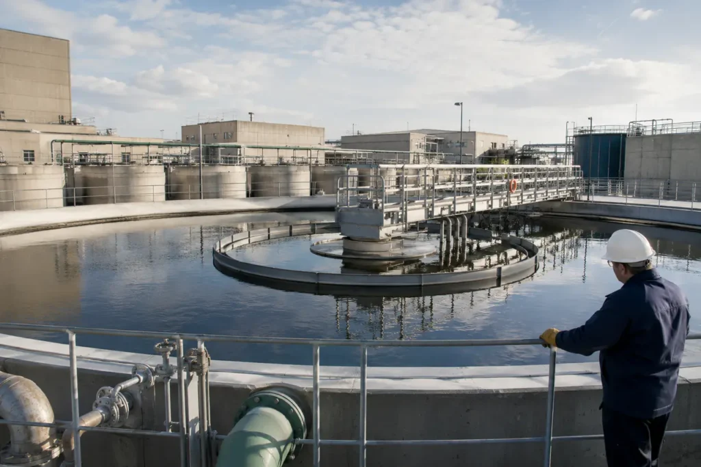
For a conventional tank, the calculation uses the plan area at the water surface. For a circular clarifier, that is usually the area inside the tank wall. For a rectangular clarifier, it is length multiplied by width.
What the number means in operation
Particles settle only when their settling velocity is greater than the upward hydraulic velocity created by the applied flow. If HLR rises too far, slower-settling particles remain suspended and leave with the clarified effluent.
That does not mean HLR alone predicts actual removal. Short-circuiting, inlet turbulence, temperature, floc strength, sludge blanket depth, and outlet weir conditions can all change performance. HLR is a design screen, not a complete process model.
A useful distinction is that HLR describes liquid movement, while Solids Loading Rate (SLR) describes the dry solids mass applied to the clarifier per unit of area and time.
A tank can pass its hydraulic check and still fail because its solids loading is too high.
- HLR: wastewater flow divided by effective clarifier surface area.
- SLR: dry solids mass applied per unit of clarifier area and time.
- WOR: flow divided by total effective effluent weir length.
- TSS removal: the observed separation result, which depends on both hydraulics and solids behavior.
For procurement teams, the important question is not simply whether a supplier lists a flow capacity. Ask whether that capacity is based on projected settling area, actual tank footprint, allowable SLR, weir loading, or a tested operating condition.
WCT’s Wastewater Clarifier overview can be used as an early equipment reference, but final sizing should be based on site flow data and influent solids characteristics rather than a nameplate flow alone.
Key Clarifier Formulas: HLR, SLR, and Weir Overflow Rate
Clarifier sizing requires HLR, SLR, and Weir Overflow Rate (WOR) to be checked together. Surface area controls hydraulic loading, while solids mass and outlet geometry can impose separate limits.
Hydraulic Loading Rate Formula
The surface settling rate formula is:
HLR = Q / A
Where Q is the design flow and A is the effective horizontal surface area. If Q is expressed in gallons per day and A in square feet, the answer is reported as gallons per day per square foot, or GPD/sq ft.
For a circular clarifier:
A = pi x D2 / 4
For a rectangular clarifier:
A = L x W
Example: a circular tank with a 50-foot diameter has approximately 1,963 square feet of surface area. At a flow of 1.0 MGD, or 1,000,000 GPD, the HLR is approximately 509 GPD/sq ft.
- Convert the flow to compatible units: 1.0 MGD becomes 1,000,000 GPD.
- Calculate surface area: pi x 50 x 50 / 4 equals approximately 1,963 sq ft.
- Divide flow by area: 1,000,000 / 1,963 equals approximately 509 GPD/sq ft.
- Compare that result with the selected clarifier type, peak condition, and solids loading check.
The same calculation in metric units is expressed as cubic meters per square meter per day, written here as m3/m2.d. Because the area units cancel, this is also equivalent to a vertical velocity expressed as meters per day.
Solids Loading Rate (SLR) and Weir Overflow Rate (WOR)
SLR is especially important for secondary clarifiers receiving activated sludge. The calculation must include the solids entering the tank, not only the raw influent flow. Return activated sludge flow and mixed liquor concentration can materially change the solids load.
| Metric | Formula | Variables Explained | Standard Units |
|---|---|---|---|
| Hydraulic Loading Rate | HLR = Q / A | Q = design flow; A = clarifier surface area | GPD/sq ft or m3/m2.d |
| Surface Area | A = pi x D2 / 4 | D = tank diameter | sq ft or m2 |
| Rectangular Area | A = L x W | L = tank length; W = tank width | sq ft or m2 |
| Solids Loading Rate | SLR = M / A | M = dry solids mass applied per day; A = surface area | lb/day/sq ft or kg/m2.d |
| Weir Overflow Rate | WOR = Q / Lw | Q = flow; Lw = effective weir length | GPD/ft or m3/m.d |
Common conversions should be completed before the calculation, not after it. One MGD equals 1,000,000 GPD. One square meter equals approximately 10.764 square feet. One GPD/sq ft equals approximately 0.0407 m3/m2.d.
For SLR, a simplified activated-sludge check may use flow, return sludge flow, and mixed liquor suspended solids concentration to estimate the mass entering the clarifier.
The exact equation depends on the plant’s flow split and whether the design basis uses average, maximum month, or peak solids loading.
WOR is calculated using the total effective outlet weir length. A tank with adequate surface area can still develop poor effluent quality if the outlet launders are short, unevenly leveled, partially blocked, or hydraulically overloaded.
After any formula is calculated, ask what it leaves out. A reported capacity based only on HLR may not include inlet energy dissipation, sludge storage volume, scraper torque, scum removal, or outlet weir limitations.
Standard Hydraulic Loading Rate Design Ranges
Typical HLR ranges vary with clarifier position, wastewater type, sludge settleability, temperature, flow basis, and local design criteria. The table below provides engineering starting points, not guaranteed performance limits.
| Clarifier Type | Typical HLR Range, GPD/sq ft | Metric Equivalent, m3/m2.d | Typical Design Notes |
|---|---|---|---|
| Primary clarifier | 300-1,200 | 12.2-48.8 | Often checked at average and peak hourly flow; detention time and scum handling remain important. |
| Secondary clarifier, activated sludge | 400-800 | 16.3-32.6 | Must be checked with SLR, SVI, return sludge flow, and sludge blanket behavior. |
| Peak wet-weather condition | 600-1,200 | 24.4-48.8 | Use only when the process, solids inventory, and effluent limits support the selected peak condition. |
| High-rate lamella or inclined-plate system | Project-specific | Project-specific | Use projected settling area and supplier-defined test or design criteria rather than conventional tank area alone. |
The primary clarifier range is broad because primary wastewater characteristics differ widely. Grease, grit, industrial discharge, temperature, and upstream screening performance can all change the HLR that produces acceptable TSS and BOD removal.
Primary clarifier parameters
Primary clarifiers are commonly evaluated using HLR, detention time, tank depth, WOR, and expected TSS removal. A higher HLR may reduce tank volume and footprint, but it gives less margin for flow surges and poor settling conditions.
- Use average daily flow to understand normal loading.
- Use peak hourly flow to assess hydraulic overloading and short-circuiting risk.
- Check detention time at both normal and peak flow.
- Review inlet distribution, baffle arrangement, and outlet weir leveling.
- Confirm that sludge and scum removal systems can keep pace with the applied load.
Secondary clarifier parameters
Secondary clarifiers require a different decision process because the incoming solids concentration is much higher. HLR may appear acceptable while SLR, sludge blanket depth, or return sludge limitations create the actual failure.
Sludge Volume Index (SVI) is a key operating input. Higher SVI generally indicates poorer settling and greater sensitivity to solids accumulation. A design that works with well-settling sludge may not work during filamentous growth, cold weather, or process upset conditions.
Peak flow limits should not be selected from the average-flow result. For municipal plants, wet-weather flow can be several times the normal operating flow. The design review should show which units operate in parallel and how the flow is divided between them.
Impact of HLR on Detention Time and TSS Removal
Increasing HLR reduces hydraulic detention time when tank volume remains constant. The basic relationship is:
Detention time = tank volume / flow
This inverse relationship explains why a clarifier may perform well during dry weather and lose TSS removal during a storm. The tank has not changed, but the flow passing through it has increased.
- Reduced settling opportunity: slower particles remain in suspension and move toward the effluent outlet.
- Increased turbulence: high inlet or outlet velocities can break floc and disturb settled solids.
- Short-circuiting: some water reaches the outlet before using the full tank volume.
- Sludge blanket rise: solids accumulate faster than they are withdrawn.
- Effluent TSS increase: solids carryover can exceed the expected treatment performance.
Hydraulic overloading in a primary clarifier can also send more suspended and organic material to downstream biological treatment. That increases the aeration basin load and may change oxygen demand, sludge production, and secondary clarifier behavior.
Where secondary clarification usually fails first
Secondary clarifiers are often limited by solids flux rather than water volume alone. State Point Analysis helps compare the applied solids flux with the settling and transport capacity of the sludge blanket.
The analysis typically uses mixed liquor concentration, return activated sludge concentration, return flow, waste sludge flow, and SVI. It can indicate whether the clarifier is operating below, near, or beyond a condition where solids will accumulate and escape.
A state point result is only as useful as the data behind it. One laboratory SVI measurement may not represent the worst daily condition. Operators should review trends across flow, MLSS, RAS rate, blanket depth, and effluent TSS.
What to review when removal drops
- Compare current HLR with average, maximum month, and peak hourly flow.
- Check whether all clarifiers are receiving an equal share of the flow.
- Measure sludge blanket depth at multiple points, not only near one probe.
- Review SVI and settleability trends during the same period as the upset.
- Inspect launders, weirs, scum baffles, inlet gates, and flow-control devices.
The expensive mistake is lowering RAS or changing wasting rates based on effluent symptoms without checking the hydraulic balance. A process adjustment can temporarily move solids, while the underlying clarifier capacity problem remains.
Sizing Considerations for Specialized Clarifiers
Slant plate and lamella clarifiers use inclined plates or tubes to create a large effective settling area within a smaller floor footprint. Their rating cannot be compared directly with a conventional tank using only plan area.
Slant plate (lamella) clarifiers
For an inclined plate pack, the relevant settling area is commonly based on the horizontal projection of the plates. A simplified relationship is:
Projected area = plate plan area x number of effective plates
Depending on the supplier’s method, the projected area may be calculated from plate width, plate length, spacing, inclination angle, and the number of channels.
The actual wetted plate surface is larger than the horizontal projected area, but that larger number should not automatically be used as the hydraulic settling area.
The inclination angle changes the vertical settling distance and supports solids sliding toward the collection zone. Plate spacing affects plugging risk, solids transport, cleaning access, and the type of wastewater the unit can handle.
- Confirm whether the stated capacity uses projected area or actual plate surface area.
- Check the design flow at normal, maximum, and peak conditions.
- Review influent TSS, oil and grease, grit, and floc size.
- Verify plate spacing against the expected solids and maintenance method.
- Ask how sludge is removed from the hopper and whether withdrawal is continuous.
A compact footprint is valuable for industrial retrofits or plants with limited available area. It does not remove the need for equalized distribution, stable feed conditions, adequate sludge withdrawal, and an outlet system that prevents localized overflow.
High-rate clarification systems
High-rate systems may combine inclined plates, tube settlers, chemical coagulation, flocculation, or internal recirculation. These features can improve separation, but they also make the design basis more dependent on feed chemistry and floc quality.
For example, a lamella unit receiving chemically flocculated water may be rated at a different loading than the same plate geometry receiving untreated industrial wastewater. The equipment footprint is not the only variable that changed; the particle settling behavior changed too.
Use the manufacturer’s projected-area calculation, test data, and operating envelope when reviewing a high-rate proposal. Compare the test water and floc conditions with the actual site. A capacity proven with stable, chemically conditioned solids may not transfer directly to a variable wastewater stream.
Where a conventional basin is being upgraded, compare the new unit against the existing hydraulic profile. The equipment may fit physically while the upstream pump, channel, valve, or downstream filter cannot accept the revised flow pattern.
For broader equipment comparisons, WCT’s DAF vs clarifier reference can help distinguish cases where flotation is more suitable than gravity settling. That choice should follow particle characteristics and process objectives, not footprint alone.
Clarifier Sizing Validation and Next Steps
Before finalizing clarifier specifications or procuring new equipment, validate HLR against peak wet-weather flow, solids characteristics, outlet hydraulics, and the actual operating sequence. The calculation should be traceable from field data to selected equipment.
Data the process review should include
- Average daily, maximum month, maximum day, and peak hourly flow.
- Number of clarifiers in service at each flow condition.
- Influent and mixed liquor TSS, MLSS, SVI, and sludge blanket trends.
- Return activated sludge flow, waste sludge flow, and estimated solids concentration.
- Tank dimensions, operating depth, inlet arrangement, weir length, and outlet elevations.
- Expected TSS and BOD removal requirements at normal and peak flow.
Final checks before approval
- Confirm that the design flow basis is clearly identified and converted into compatible units.
- Recalculate HLR using the active surface area, not the total site area or empty tank area.
- Check WOR using the effective weir length and confirm that the outlets are level and unobstructed.
- Review SLR and state point behavior for secondary clarifiers under the highest credible solids load.
- Test detention time at both normal flow and peak flow.
- For lamella systems, verify projected settling area, plate spacing, inclination, and sludge withdrawal capacity.
Ask suppliers to provide the calculation basis behind the quoted capacity. The useful documents include a dimensioned process drawing, flow split assumptions, loading calculations, design conditions, test data where available, and clearly stated exclusions.
For an existing plant with rising effluent TSS, do not assume a larger tank is the only answer. Hydraulic balancing, weir correction, flow equalization, improved sludge withdrawal, or a high-rate retrofit may solve different parts of the problem.
WCT can help review clarifier sizing assumptions, compare conventional and inclined-plate configurations, and identify the field data needed for a retrofit decision. The strongest starting package is a flow record, solids trend, tank drawing, and current operating problem stated in measurable terms.