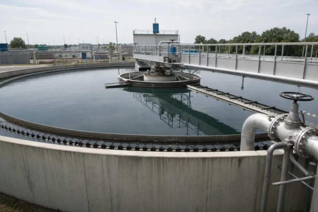
A wastewater clarifier is often the threshold between a treatment plant that runs predictably and one that chokes on its own solids inventory.
When gravity settling fails to produce a clean overflow and a dense underflow, everything downstream-aeration, filtration, disinfection-loses its operating window.
This guide works through the design logic, stage-specific demands, hardware geometries, and the site data that drive a tight clarifier specification.
What is a Wastewater Clarifier & How It Works
Modern wastewater clarifier systems are large, continuously operated sedimentation tanks that use gravity to separate suspended solids from a liquid stream.
The process yields two outputs: a clarified effluent that exits over weirs at the top, and a thickened sludge that concentrates at the bottom for removal.
In a municipal or industrial flow sheet, the clarifier sits between biological or chemical stages and the final solids-handling train.
Two hydraulic conditions control performance. The particle settling velocity must consistently exceed the upward liquid velocity created by the tank’s overflow rate. When those numbers invert-often during a peak wet-weather surge-solids carry over into the effluent.
The Mechanics of Gravity Sedimentation
In a continuously fed tank, particles settle into four zones:
- Clear supernatant at the top
- Hindered settling zone in the middle
- Transition zone
- Compaction zone at the floor
Type I settling (discrete particle settling) dominates in primary clarifiers; Type III (zone settling) is typical in secondary clarifiers where biological floc blankets form.
Designers target a surface overflow rate (SOR) that keeps the rise rate comfortably below the particle settling velocity.
A typical primary clarifier SOR falls in the range of 30-50 m3/m2·day at average flow, tightening to 20-30 m3/m2·day for secondary units handling lighter floc.
Exceed those numbers and the effluent launder becomes a solids bypass.
The Role of Enhanced Particle Flocculation
Raw wastewater contains a broad particle size distribution. Fine colloidal solids-clays, emulsified oils, low-density organics-settle slowly or not at all under gravity alone.
That’s why most plants inject a coagulant (iron or aluminum salts) or a long-chain polymer upstream of the clarifier. The chemicals bind small, stable particles into larger, denser flocs that settle two to five times faster.
Typical coagulant and flocculant families include:
- Iron salts (ferric chloride, ferric sulfate)
- Aluminum salts (alum, polyaluminum chloride)
- Organic polymers (anionic, cationic, or non-ionic)
Flocculation design matters. A poorly sized flocculation chamber that shears forming flocs wastes chemical cost without improving capture. In practice, operators verify floc size and settleability with a jar test that mirrors the plant’s mixing energy and detention time before tuning polymer dose.
Primary vs. Secondary Clarification
Clarifiers appear at two distinct points in a conventional activated-sludge plant, and confusing the two leads directly to mis-specification.
Primary units receive raw sewage after screens and grit removal; secondary units receive mixed liquor from the aeration basin.
The solids type, loading, and required effluent quality are different, so the tank hydraulic design and mechanical hardware must match the stage.
| Parameter | Primary Clarifier | Secondary Clarifier |
|---|---|---|
| Process Goal | Reduce BOD/TSS load sent to aeration; separate heavy, raw settleables | Separate biological floc from treated effluent; return or waste sludge |
| Placement in Train | After preliminary treatment (screens/grit), before aeration | After aeration basin, before disinfection or filtration |
| Dominant Solids Type | Dense inorganic and organic solids (sand, grit remnants, fecal matter, food waste) | Light, buoyant microbial floc (activated sludge with high water content) |
| Typical Hydraulic Retention Time | 1.5-2.5 hours | 2.0-3.5 hours |
| Expected BOD/TSS Reduction | 25-40% BOD, 50-70% TSS | Effluent typically <30 mg/L BOD and TSS (permit-dependent) |
Primary Clarifiers: Initial Solids Removal
A primary clarifier takes the first swing at the plant’s suspended solids and organic load. It captures the fast-settling fraction-grit that escaped the grit chamber, heavy organic particles, and floatable grease.
By pulling 30-40% of the BOD load out early, the clarifier lowers aeration energy demand and reduces the sludge age pressure on the biological stage. Scum skimmers and sludge hoppers operate at the same time, pulling floatables and settled solids toward collection troughs.
Primary sludge is typically pumped to gravity thickeners or directly to anaerobic digesters. Because this sludge is dense and often contains abrasive grit, the sludge removal mechanism (usually a chain-and-flight or rotating scraper) must tolerate grit wear.
Sedimentation tanks at this stage are often designed with a rectangular profile when shared-wall construction lowers civil cost on a compact site.
Secondary Clarifiers: Biological Floc Separation
The secondary clarifier does double duty: it must produce an effluent clean enough for discharge or filtration, and it must reliably thicken the settled activated sludge for return (RAS) or wasting (WAS).
Biological floc is fragile; high hydraulic turbulence or a fast-moving scraper can break floc into pin particles that wash over the weir.
That’s why secondary clarifiers are often designed with deeper sidewater depths (3.5-5 m) and conservative SORs, especially at peak flow.
A poorly sized secondary clarifier can lose its sludge blanket in a rain event. Once the blanket rises above the optimum 0.3-0.9 m depth and approaches the weirs, solids escape.
Many plants now install sludge blanket level monitors tied to RAS pump speed to keep the interface stable under variable flow.
Types of Clarifiers (Design and Technology Comparison)
For plant-scale clarifier applications, three physical geometries cover the majority of installations. The right shape depends less on tradition and more on available footprint, sludge characteristics, and the cost of civil construction.
| Clarifier Type | Footprint | Sludge Removal Mechanism | Ideal Application | Relative Capital Cost |
|---|---|---|---|---|
| Circular | Large diameter; typically 15-60 m for municipal units | Rotating scraper arms driven by a center column drive | Large municipal secondary clarification; high-capacity primary units | Medium to high (concrete basin, torque-loaded drive) |
| Rectangular | Long, narrow channels; allows common-wall construction | Chain-and-flight collectors or traveling bridge scrapers | Space-constrained retrofits; large plants with multiple units | Medium (shared walls reduce concrete volume) |
| Inclined Plate/Tube Settlers | Very compact; vertical stacked plates or tubes | Gravity hopper or screw auger; minimal mechanical movement | Industrial pretreatment; retrofit capacity upgrades; low-flow polishing | Lower equipment cost; may need upstream chemical coagulation |
Circular Clarifiers
The circular clarifier mechanism relies on a center-fed or peripheral-fed inlet that radiates outward. Rotating scraper arms continuously push settled sludge toward a central hopper while a surface skimmer directs floatables to a scum box.
The drive unit, usually a low-speed gear reducer with a torque-sensing arm, is the single highest-maintenance component. If the scraper encounters a compacted sludge mound, torque spikes trigger an alarm or automatic rake lift.
Circular tanks work well when the site has square area to spare and when a single, high-capacity unit is preferred. They scale easily: diameters up to 60 m are common in large municipal secondary applications.
However, the radial flow geometry can create short-circuiting if the inlet baffle or stilling well isn’t sized correctly.
Rectangular Clarifiers
Rectangular clarifiers use long concrete channels, typically 3-6 m wide and up to 90 m long, with a chain-and-flight collector system. Flights drag settled sludge to a hopper at the influent end, while the return loop carries the flight back near the surface.
Shared-wall construction makes rectangular basins cost-effective when a plant needs multiple parallel units; you pour walls once and line them up side by side.
The weak point is chain tension and wear. Operators track flight alignment, sprocket tooth condition, and tensioner position weekly.
A snapped chain that drops flights into the basin floor stops the unit and can damage the effluent weir troughs.
Many plants keep a spare set of flights and chain links on-site for quick replacement during low-flow windows.
Inclined Plate and Tube Settlers
Inclined plate settlers pack multiple parallel plates at a 45-60° angle into a compact basin, multiplying the effective settling area by the projected horizontal area of each plate.
The same principle applies to tube settler media, where honeycomb-shaped tubes provide high surface area in a vertical stack.
These systems achieve a SOR equivalent to a much larger conventional clarifier in a footprint roughly one-tenth the size.
The trade-off is sensitivity to floc quality. Without a stable, well-formed floc from upstream coagulation, lightweight particles bypass the plates. Lamella clarifiers are most common in industrial metal hydroxide precipitation, cooling tower blowdown treatment, and as retrofit capacity boosters in existing conventional basins.
Periodic acid cleaning of the plate packs is required to remove scale buildup that can reduce effective settling area.
Key Factors When Selecting a Clarifier System
Choosing between a circular, rectangular, or plate-based system comes down to three interacting limits: how much water you must move, how much space you have, and what the solids will do inside the tank. The right selection prevents these four common specification misses:
- Hydraulic loading rate (HLR) and surface overflow rate at peak flow. A clarifier sized for average daily flow can fail during a 1-hour storm surge. Engineers verify that peak SOR stays below the settling velocity of the critical particle size, usually 30-50 m3/m2·day for primary units and lower for secondary units. If peak wet-weather flow doubles average flow, the clarifier may require a larger surface area or a side-stream storage equalization basin.
- Site footprint and civil constraints. Retrofitting a rectangular unit into an existing plant with tight lane widths can be cheaper than demolishing structures for a large circular basin. In greenfield plants, circular tanks may reduce mechanical complexity. Always map the available rectangle or diameter before choosing a geometry.
- Solids loading rate and sludge handling. A clarifier that settles solids well still fails if the sludge removal system can’t move the mass. A primary unit receiving heavy grit needs a robust scraper; a secondary unit returning RAS at 50-100% of influent flow needs a drive that handles variable torque. Match the underflow pump capacity to the projected sludge volume, including peak-day solids loading.
- Materials of construction. Concrete basins with 304 or 316 stainless steel mechanisms are the norm for permanent municipal installations. Industrial sites with corrosive low-pH wastewater or high chlorides often require coated steel or duplex stainless wetted parts. Packaged steel clarifiers can be factory-welded and shipped for quick deployment but may need sacrificial anodes or epoxy lining in aggressive environments.
Before finalizing a selection, cross-check these operational details:
- Run a jar test on representative influent to confirm floc settling velocity matches the design SOR.
- Model the clarifier hydraulics at peak wet-weather flow to rule out short-circuiting paths.
- Confirm the sludge removal system torque capacity meets the expected peak solids load.
- Verify that materials of construction (MOC) withstand the corrosive potential of the wastewater chemistry.
Clarifier Maintenance Best Practices
Most clarifier downtime originates in the mechanical drive or the sludge removal train. A regular preventive maintenance program that inspects these three subsystems during low-flow windows prevents the midnight call-out.
Drive Unit and Torque Monitoring
Routine drive maintenance prevents the most common source of clarifier downtime. Key checks include:
- Remove condensate from the drive housing; water in oil degrades gears quickly.
- Lubricate the main bearing and pinion gear per the manufacturer interval (typically every 400-800 operating hours).
- Monitor torque readings weekly. An upward trend may indicate compacted sludge or mechanical bind.
- If equipped with an automatic rake lift, cycle it and check for free movement without jamming.
Sludge Removal System Upkeep
In rectangular basins, chain-and-flight systems need monthly tension checks. A loose chain can skip a sprocket and lock the collector. Inspect wear strips and rail liners for thinning; replace when they approach half the original thickness.
For rotating scraper arms, inspect the squeegee blades and replace when they no longer make full contact with the floor slope. A gap of a few millimeters leaves a sludge layer that eventually goes septic, causing odor and buoyant floc problems up-current.
Effluent Weir and Launder Cleaning
Uneven weir loading creates local high-velocity currents that pull solids over the edge. Algae growth on V-notch weirs increases the effective weir height, concentrates flow to clean sections, and distorts the tank’s hydraulic profile.
A bi-weekly brush cleaning combined with occasional pressure washing keeps weirs level. In outdoor plants, adding an aluminum weir cover reduces sunlight and slows algae regrowth between service rounds.
What to Prepare Before System Design & Sizing
A clarifier specification is only as tight as the site data it’s built on. Before moving to detailed design, bring together the following load points so the application team can size the basin geometry, drive torque, and sludge removal capacity correctly.
- Average daily flow and peak-hour flow rates, plus the diurnal flow pattern if it swings more than 30% off average.
- Influent TSS and BOD concentrations, including a seasonal high-limit and a typical low to establish the design range.
- Available site footprint dimensions-not just the basin area, but access for sludge pump piping and future maintenance crane clearance.
- Existing sludge handling path: where will primary/secondary sludge be pumped, and at what distance/static head?
- Any chemical pretreatment chemicals (coagulant and polymer types) already in use, so the settling character can be referenced in a jar test.
When you’re ready to advance from preliminary layout to a sized specification, our application engineers can build a configuration that matches your hydraulic constraints and mechanical load envelope.
Send in the data sheet, and we’ll start the sizing discussion with a process flow sketch and a torque-duty estimate.