When a major Permian operator we work with hit its saltwater disposal well capacity mid-season, trucking costs alone added $2.80 per barrel to their opex. That’s the kind of trigger that transforms produced water treatment from a regulatory checkbox into a core operational decision. We’ve watched seismic risk maps and saltwater disposal injection curtailments rewrite field economics faster than most engineers realize.
If you’re still designing water management plans around unlimited deep-well access, you’re missing a fundamental shift. The industry’s future lies in treating produced water as a resource stream — not a waste. We’ll walk through the exact technology stack, selection logic, and maintenance disciplines that separate profitable reuse operations from stranded asset nightmares.
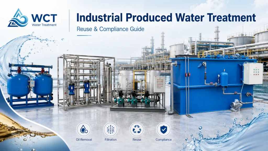
What is Produced Water and Why Treatment is Critical for Modern Operations
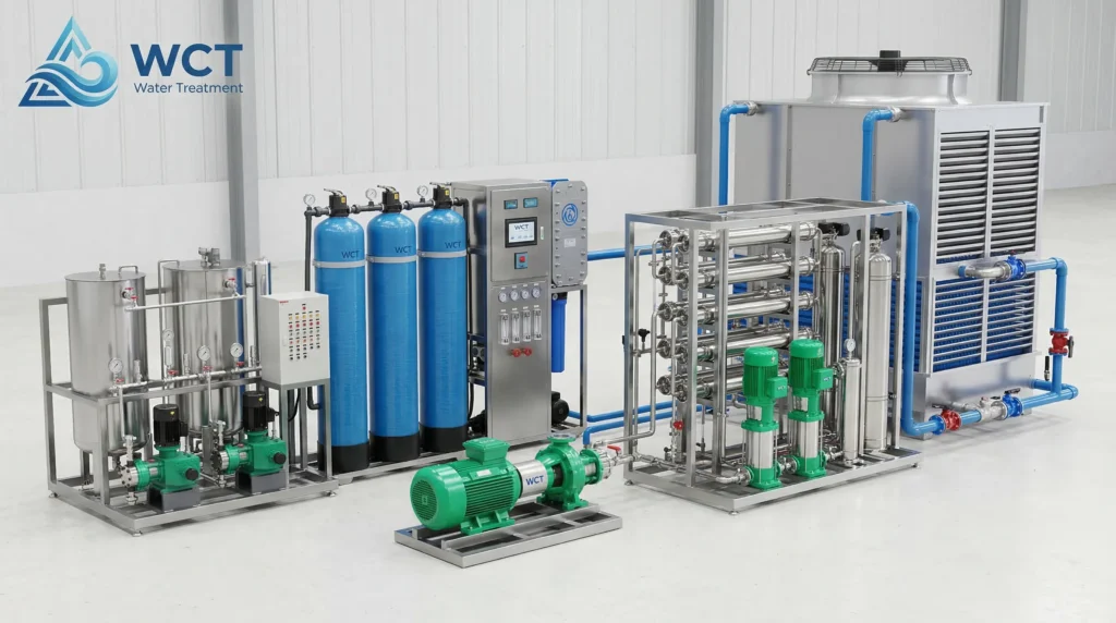
Produced water is the largest byproduct stream in oil and gas extraction, requiring specialized produced water treatment to remove hydrocarbons, suspended solids, and dissolved salts before discharge, reinjection, or beneficial reuse. Untreated, this wastewater can cause formation damage, violate surface discharge limits, or render enhanced oil recovery ineffective. At WCT Water Treatment, we design integrated industrial water treatment systems that turn this liability into a managed asset.
Flowback Water vs. Produced Water: Key Chemical Variations
The terms are often used interchangeably, but the engineering reality is stark. Flowback water returns to the surface within days to weeks after hydraulic fracturing, containing a mix of injected chemicals, proppants, and varying salinity that can escalate quickly. Produced water, by contrast, is the long-term formation water that flows with the hydrocarbons over the well’s productive life. It’s characterized by extreme total dissolved solids (TDS) — sometimes exceeding 300,000 mg/L — along with dissolved gases and naturally occurring radioactive materials (NORM).
Engineering takeaway: Flowback can often be treated with simpler filtration and chemical precipitation because of its lower TDS and more predictable chemistry. Produced water demands multi-stage treatment process for produced water to handle both organic and inorganic loads simultaneously.
| Parameter | Flowback Water | Produced Water |
|---|---|---|
| Primary Source | Hydraulic fracturing fluid returns | Formation water co‑produced with oil/gas |
| Timeframe | First 2‑6 weeks after well completion | Entire well production life (years) |
| Typical TDS range | 5,000 – 80,000 mg/L | 40,000 – 300,000+ mg/L |
| Key organic contaminants | Friction reducers, biocides, gel residues | BTEX, organic acids, residual oil emulsions |
| Treatment priority | Polymer breakdown, solids removal | Desalination, organics polishing, NORM sequestration |
Note: TDS ranges are field-dependent. Complete water chemistry analysis is required before selecting any treatment train.
The Operational Drivers: Disposal Constraints, Seismic Risks, and Reuse Incentives
Conventional deep‑well injection — the historic go‑to for produced water — is hitting a regulatory wall. In the Permian and Arbuckle basins, induced seismicity tied to saltwater disposal (SWD) wells has led to injection rate cuts and outright shut‑ins. Simultaneously, trucking and pipeline tariffs for off‑site disposal have spiked, squeezing single‑digit operating margins. These constraints push operators toward on‑site treatment and beneficial reuse strategies, whether for enhanced oil recovery (EOR), hydraulic fracturing fluid makeup, or even agricultural water supply after high‑level polishing. For procurement and compliance managers, the question has shifted from “Can we afford to treat?” to “Can we afford not to treat?”
The Multi-Stage Produced Water Treatment Process Architecture
Effective produced water treatment requires a multi‑stage process — progressing from primary bulk oil separation to secondary emulsion breaking, and finishing with tertiary polishing to remove dissolved organics and fine solids. Skipping any stage risks catastrophic fouling downstream, especially where membrane bioreactor (MBR) or advanced membrane filtration for produced water systems are deployed.
Primary Treatment: Gravity Separation, Hydrocyclones, and Stokes’ Law
We always begin with bulk separation governed by Stokes’ Law: the rise velocity of an oil droplet is directly proportional to the square of its diameter and the density differential between oil and water. In practice, this means engineered gravity separators (API and plate‑pack interceptors) and hydrocyclones are sized to remove free oil droplets larger than about 60 microns. A well‑designed primary stage lifts 90‑95% of free and emulsified oil that would otherwise destroy downstream membranes and coalescing media. For compact installations, we frequently specify inclined plate settlers to maximize separation surface area without large‑footprint basins.
Secondary Treatment: Induced Gas Flotation (IGF) and Coalescing Media
Induced gas flotation (IGF) units use dispersed gas bubbles — typically nitrogen, natural gas, or carbon dioxide — to float remaining fine oil droplets and suspended solids to the surface for skimming. By introducing bubbles much smaller than those in atmospheric flotation, IGF accelerates the ascent of droplets below 20 microns, effectively breaking free and emulsified oil emulsions that survived primary separation. We often pair IGF with proprietary coalescing media that forces small oil droplets to collide and aggregate, dramatically increasing removal efficiency while reducing chemical coagulant demand.
- Engineering advantage: No ambient air introduction, eliminating explosive atmospheres in enclosed hydrocarbon processing.
- What to verify: Gas‑to‑water ratio control and media life expectancy under high‑TDS scaling conditions.
Tertiary Treatment: Media Filtration, Polymeric Adsorbents, and Ultrafiltration
Once bulk and emulsified oil are removed, the water still contains dissolved hydrocarbons, colloidal solids, and trace metals. Tertiary treatment polishes to <10 mg/L oil‑and‑grease and non‑detectable TSS. We deploy multimedia sand media filters or nutshell filters for solids, followed by polymeric adsorbents that remove BTEX and other soluble organics through hydrophobic interaction. For the tightest polish before desalination, ultrafiltration (UF) membranes provide a barrier against residual oil and bacteria, extending the life of downstream reverse osmosis elements significantly.
Best‑fit scenario: High‑organics produced water targeting reuse as fracking fluid requires at minimum UF or adsorbent polishing. Without it, even minor oil carryover can foul RO membranes irreversibly within days.
Advanced Desalination and Thermal Technologies for High-Salinity Streams
High‑salinity produced water exceeding 40,000 mg/L total dissolved solids (TDS) typically requires thermal evaporation or specialized high‑pressure membrane separation, because standard reverse osmosis becomes thermodynamically restricted. We evaluate both energy and chemical costs when selecting the desalination backbone of a designing a produced water treatment system.
Membrane Desalination: Reverse Osmosis (RO) and Nanofiltration
Reverse osmosis (RO) is the workhorse for lower‑salinity produced waters (< 40,000 mg/L TDS). But as salinity climbs, the osmotic pressure opposing the applied hydraulic pressure grows prohibitively. At 45,000 mg/L TDS, typical brackish RO membranes require feed pressures above 1,200 psi, pushing into costly high‑pressure pump territory and increasing energy consumption to 5‑7 kWh/m³. Nanofiltration (NF) selectively removes divalent scale‑forming ions (Ca²⁺, SO₄²⁻, Ba²⁺) at lower pressure, making it a valuable pre‑treatment step ahead of thermal units or when partial softening is sufficient for reuse. We often deploy a UF‑NF‑RO cascade to balance flux with membrane longevity.
Thermal Concentration: Mechanical Vapor Recompression (MVR) and Evaporators
For the extremely high TDS streams — up to 300,000 mg/L — mechanical vapor recompression (MVR) evaporators become the practical workhorse. MVR compresses the vapor generated during boiling, reusing its latent heat to drive further evaporation. This cuts the net energy consumption to as little as 15‑25 kWh/m³ of distillate, roughly one‑tenth that of single‑effect evaporators. When achieving zero liquid discharge (ZLD) is mandated, we follow MVR with a brine crystallizer, producing a solid salt cake that can be disposed of in nonhazardous landfills while recovering over 98% of the water as high‑purity distillate. The capital cost is steep — often $1‑3 million per 1,000 bpd — but the elimination of liquid waste hauling can deliver payback in under three years under high‑disposal‑fee scenarios.
Decision rule: When TDS exceeds 60,000 mg/L, our TCO models nearly always favor MVR over high‑pressure RO due to membrane replacement costs and downtime risk.
Emerging and Novel Treatment Technologies for Beneficial Reuse
Emerging produced water treatment methods leverage osmotic pressure differentials and electrical fields to desalinate highly concentrated brines with lower thermal footprints than conventional evaporators. While still scaling, these technologies are already being deployed in pilot and demonstration projects, especially where beneficial reuse for agriculture or surface discharge drives the water quality target.
Osmotically Driven Membranes: Forward Osmosis (FO) and Membrane Distillation (MD)
Forward osmosis (FO) uses a highly concentrated draw solution (often ammonium bicarbonate or high‑salinity brine) to pull clean water across a semi‑permeable membrane without requiring high hydraulic pressure. The draw solution is then regenerated thermally to recover the product water. This drastically reduces membrane fouling because no hydraulic compaction occurs, making FO attractive for high‑fouling produced waters loaded with free and emulsified oil. Membrane distillation (MD) applies a temperature gradient across a hydrophobic membrane; water vapor passes through while liquid brine and contaminants are retained. MD can handle TDS up to saturation and integrates well with waste heat from compressor stations.
- Procurement concern: FO and MD equipment remains niche, with fewer proven at‑scale references compared to RO and MVR. We advise rigorous pilot testing before capital commitment.
Electrodialysis Reversal (EDR) and Electrodeionization (EDI)
Electrodialysis reversal (EDR) uses ion‑exchange membranes and an electrical current to pull salt ions from the feed into a concentrate stream. It excels at mid‑range TDS (5,000‑15,000 mg/L) where RO would be overkill and simple media filtration insufficient. EDR’s ability to reverse polarity periodically cleans the membrane surface, mitigating organic fouling. For polishing after EDR, electrodeionization (EDI) combines ion‑exchange resins with electro‑dialysis to produce ultra‑pure water with resistivity above 10 MΩ‑cm — beneficial for niche reuse in hydrogen production or cooling‑tower makeup that demands very low conductivity.
Regulatory Compliance and Discharge Standards for Onshore and Offshore Sites
Regulatory compliance demands strict adherence to localized standards, typically limiting oil and grease discharges to under 29 mg/L for offshore installations and requiring comprehensive desalination for onshore surface discharge. We’ve seen projects stalled for months because the permitting pathway wasn’t mapped before the treatment plant design was finalized.
Onshore Permitting: NPDES and Clean Water Act Requirements
For onshore surface discharge in the U.S., the National Pollutant Discharge Elimination System (NPDES) permit under the Clean Water Act sets numeric limits for oil and grease (usually 10‑15 mg/L daily max), TDS, chloride, and specific heavy metals depending on receiving water body classification. Several states, including California and Colorado, have developed general permits for produced water reuse in agriculture, but these require extensive toxicity testing (Whole Effluent Toxicity or WET) and monitoring for boron, which can be crop‑toxic at low concentrations. We recommend running a full priority pollutant scan early — not just TPH — because unknown constituents can trigger supplemental permit requirements that delay operation by 6‑12 months.
Offshore Discharge: OSPAR Regulations and Over-the-Side Oil-in-Water Limits
In the North Sea and many international offshore jurisdictions, OSPAR regulations cap over‑the‑side oil‑in‑water concentrations at 30 mg/L monthly average. The Gulf of Mexico allows up to 29 mg/L as a monthly average under U.S. EPA guidelines. Real‑time optical monitors (UV fluorescence) are essential; grab sampling alone can miss transient spikes during separator upsets. Compact offshore water treatment trains rely on hydrocyclones followed by induced gas flotation units to stay below this threshold, because space and weight constraints prohibit large‑scale desalination.
Buyer warning: Don’t assume a discharge limit is the only target. Some offshore operators must also meet zero liquid discharge (ZLD) if reinjection into the well is specified for reservoir pressure maintenance, adding a crystallizer stage.
Economic Evaluation: Disposal (SWD) vs. Treatment and On-Site Reuse
While deep‑well injection remains the historical low‑cost baseline, rising transportation tariffs, regulatory injection limits, and seismic risks are making on‑site treatment and regional midstream recycling pipelines more economically viable. The right model depends on an honest total cost of ownership (TCO) analysis — one that doesn’t just look at per‑barrel disposal fees.
Saltwater Disposal (SWD) Lifecycle Costs and Capital Demands
A typical SWD well in the Delaware Basin might cost $3‑5 million upfront, with annual operation and maintenance (O&M) of $0.10‑$0.30 per barrel injected. But that figure excludes hauling — commonly $0.50‑$2.00 per barrel depending on distance — and the risk of mandated volume curtailments. When both are factored in, our clients often see effective SWD cost creep to $1.50‑$3.00/bbl. And that’s without accounting for seismic liability. A single Class II injection well shutdown due to induced seismicity can strand hundreds of thousands of barrels per day, forcing expensive emergency trucking to distant facilities.
The Midstream Water Paradigm: Dedicated Pipelines and Shared Recycling Infrastructure
A growing network of dedicated produced water gathering pipelines and centralized recycling hubs in the Permian has shifted water management from a localized headache to a shared logistics infrastructure. These midstream operators aggregate produced water from multiple operators, treat it to a spec suitable for fracturing, and sell it back at $0.30‑$1.00 per barrel — often cheaper than fresh water sourcing plus disposal. For larger players, investing in water recycling infrastructure that uses UF/RO or MVR to produce reusable brine can lock in supply for EOR and fracking while eliminating SWD dependence entirely.
| Treatment Objective | Typical Cost Range (per barrel) | Key Cost Drivers | Typical Use Case |
|---|---|---|---|
| Filtration for SWD injectivity | $0.10 – $0.30 | Coarse solids removal, basic oil skimming | Pre‑injection to avoid well plugging |
| Reuse for hydraulic fracturing | $0.50 – $1.50 | UF, oxidation, scale inhibitor, limited desalination | Match‑spec water for frac fluid blending |
| Beneficial reuse (irrigation/discharge) | $1.50 – $3.00 | Full desalination, organics polishing, toxicity testing | Agricultural agricultural water treatment or surface discharge |
| Advanced thermal ZLD | $2.00 – $4.00 | MVR + crystallizer, energy cost, solid waste disposal | No‑liquid‑discharge mandates or high‑recovery reuse |
Note: Costs are approximate, based on 2024‑2025 Permian Basin project data. Actual costs depend on water chemistry, energy prices, and scale. Verify with a detailed feasibility study before budgeting.
Engineering Selection Matrix: Matching Technology to Water Characteristics
Engineers must select produced water treatment technologies based on a precise analysis of influent total dissolved solids (TDS), the ratio of free-to-emulsified oil, and physical footprint limits. A mismatch — for example, sending high‑TDS water through an unhardened RO membrane — results in rapid scaling and costly membrane replacement.
Treatment Selection by Influent TDS and Oil Concentration
We structure our preliminary selection around a classification matrix that considers two primary variables: bulk TDS and the dominant oil phase. The following table summarizes the recommended treatment train structure for typical profiles.
| Influent Profile | Primary Treatment | Secondary/Polishing | Desalination Approach |
|---|---|---|---|
| Low TDS (<20k), high free oil | Hydrocyclones + API separator | IGF or DAF for produced water treatment | UF + brackish RO (if needed) |
| Mid TDS (20‑40k), high emulsified oil | Gravity + heated emulsion breaking | Coalescing media + polymeric adsorbents | NF + low‑pressure RO or EDR |
| High TDS (40‑250k), moderate oil | Compact IGF (offshore) or gravity (onshore) | Media filtration + ultrafiltration | MVR with optional brine crystallizer |
| Ultra‑high TDS (>250k) with scaling ions | Oil‑water separation + chemical softening | UF + antiscalant conditioning | MVR + crystallizer (ZLD) or FO pilot |
What to verify: Always run a field jar‑test or bench‑scale treatability study. Organic‑laden waters can blind membranes even within “safe” TDS ranges.
Operational Footprint and Weight Constraints: Onshore vs. Offshore
Offshore platforms and floating production units place severe weight and space limits on treatment equipment. A 1,000‑bpd induced gas flotation (IGF) skid may weigh 15,000‑20,000 lbs, while an equivalent onshore DAF installation can spread across a much larger concrete pad. That’s why offshore systems favor compact hydrocyclones followed by vertical IGF vessels, sometimes augmented with membrane bioreactor (MBR) units for biological polishing before overboard discharge. Onshore, we have the luxury of large‑footprint gravity separators, extensive chemical treatment reservoirs, and MBR membrane bioreactor systems that provide robust organic removal prior to desalination. The difference in available real estate fundamentally dictates the process intensification required.
Common Failure Modes and Operational Maintenance in Treatment Plants
The primary operational failure modes in advanced produced water treatment plants are membrane biofouling from dissolved organics and severe mineral scaling from supersaturated barium, strontium, and calcium ions. We’ve seen operators lose an entire RO train in two weeks because pre‑treatment oil skimming was undersized.
Managing Membrane Biofouling and Hydrocarbon Clogging
Even trace oil — just 2‑5 mg/L — can coat RO and nanofiltration membranes with a hydrophobic film that resists cleaning and reduces permeate flux by 30‑50% within days. The fix is absolute: maintain an oil‑sensitive pre‑treatment barrier that achieves <1 mg/L non‑detectable prior to any membrane step. We often specify online oil‑in‑water analyzers upstream of the UF feed and link them to an automatic divert valve; if oil exceeds the threshold, the stream is recycled back to the IGF. Additionally, biofouling occurs when biodegradable dissolved organics (BOD/COD) feed microbial growth on membrane surfaces. A properly operated membrane bioreactor (MBR) stage ahead of desalination can consume these organics, reducing fouling potential. Regular clean‑in‑place (CIP) protocols using enzymatic cleaners or low‑pH alkaline solutions restore performance, but prevention through consistent pre‑treatment is always cheaper.
- Common mistake: Delaying membrane autopsy after a pressure drop. Early diagnosis can save $50,000+ in elements.
Scale Mitigation: Tackling Calcium Carbonate, Barium, and Strontium
Scaling from barium sulfate (BaSO₄) and strontium sulfate (SrSO₄) is particularly devastating because these scales are extremely insoluble — they resist standard acid CIP and often require mechanical scraping or complete membrane replacement. We insist on rigorous chemical dosing for produced water with optimized antiscalant blends and, for high‑risk waters, ion exchange softening upstream. Warning signs include a steady increase in differential pressure across membrane elements, reduced heat transfer coefficients in MVR evaporators (indicating scale on heat exchanger surfaces), and rapidly declining permeate quality. Real‑time monitoring of total dissolved solids (TDS), Ca²⁺, Ba²⁺, and Sr²⁺ in the feed, along with saturation index modeling (e.g., Stiff & Davis), allows proactive adjustment of water treatment chemicals before scaling takes hold.
Buyer warning: Do not select an antiscalant solely on price. BaSO₄‑specific inhibitors must be proven at the exact temperature and pH of the process through dynamic scale loop testing; we’ve seen generic products fail spectacularly in high‑TDS brines.
Develop a Custom Produced Water Treatment Strategy
Scaling up a produced water treatment facility requires rigorous bench‑scale testing, chemical modeling, and pilot deployment to ensure the design meets long‑term operational and compliance goals. At WCT Water Treatment, we start every engagement by aligning on three non‑negotiable data points: water chemistry, discharge spec, and volumetric profile. Without those, even the most advanced produced water treatment equipment becomes a guess.
Before you contact an engineering firm or an integrated supplier like us, prepare the following:
- Average and peak flow rates (bpd): Determine both daily sustained rates and short‑term slugs (frac hits, well unloading) that could overwhelm surge tanks.
- Complete water chemistry analysis: Include TDS, total organic carbon (TOC), total suspended solids (TSS), individual ions (Na⁺, Cl⁻, Ca²⁺, Mg²⁺, Ba²⁺, Sr²⁺, Fe, HCO₃⁻, SO₄²⁻), BTEX, and NORM activity.
- Target water quality specification: Define exactly the reuse goal — whether it’s 50 mg/L TDS for once‑through cooling, <500 mg/L for irrigation, or ultra‑pure for boiler feed — and cite the relevant regulatory discharge limits.
- Site constraints: Available footprint, weight limits, electrical capacity, and the presence of existing gas/steam for thermal integration.
Our team then runs a treatability trial using small‑scale replicates of the proposed train, collecting data on chemical consumption, membrane flux decline, and waste residuals. Only after pilot confirmation do we lock the P&ID and move to detailed produced water treatment solutions design. This approach has cut startup time by 40% on recent Permian midstream projects while avoiding expensive post‑commissioning retrofits.
Frequently Asked Questions
What is the average cost per barrel for produced water treatment?
Costs vary widely depending on treatment goals: disposal filtration can cost $0.10–$0.30 per barrel, reuse for fracturing may cost $0.50–$1.50 per barrel, and advanced thermal desalination for surface discharge can exceed $2.00–$4.00 per barrel. These figures include amortized capital, chemicals, energy, and O&M but exclude regional transportation tariffs.
How does induced gas flotation (IGF) differ from dissolved air flotation (DAF)?
Induced gas flotation (IGF) uses natural gas, nitrogen, or carbon dioxide to prevent explosive gas mixtures in hydrocarbon‑rich environments, whereas DAF uses compressed ambient air and is typically reserved for non‑hydrocarbon municipal or industrial wastewater. For produced water, IGF is the standard because it avoids adding oxygen that could cause corrosion or safety hazards.
What are the main contaminants in oilfield produced water?
The primary contaminants include: free and emulsified oil, suspended solids (sands, clays), high levels of dissolved inorganic salts (chlorides, sodium, calcium), heavy metals (barium, strontium, boron), dissolved gases (H₂S, CO₂), and naturally occurring radioactive materials (NORM). Each dictates a different treatment stage.
Can produced water be safely reused for agricultural irrigation?
Beneficial reuse in agriculture is being piloted, but it requires extensive desalination and complete removal of toxic organic compounds, heavy metals, and boron, which can stunt crop growth. Regulatory standards for crop irrigation are exceptionally high, and full‑scale projects demand rigorous toxicity testing and ongoing crop monitoring.
Why are barium and strontium problematic in membrane filtration systems?
Barium and strontium readily form sulfate scales — barium sulfate (BaSO₄) and strontium sulfate (SrSO₄) — which are highly insoluble and nearly impossible to remove with standard acid or alkaline clean‑in‑place (C