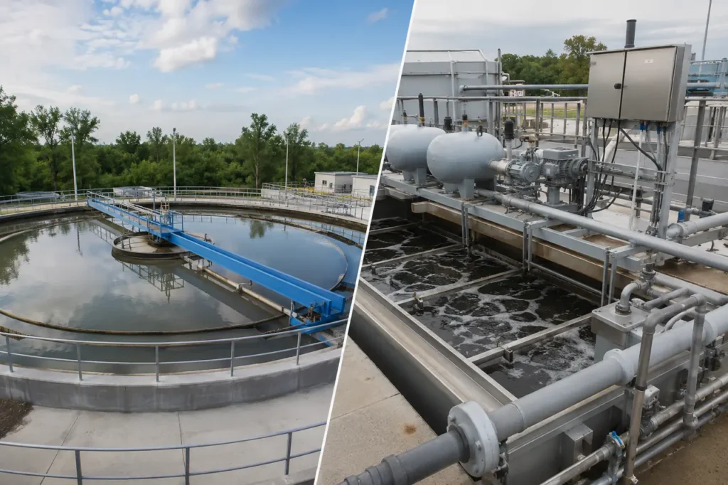
Choosing between a clarifier vs DAF system hinges on one fundamental parameter: the specific gravity of your suspended solids. If contaminants readily settle under gravity, a sedimentation clarifier provides energy-efficient separation.
If target solids float, carry neutral buoyancy, or contain fats, oils, and grease, dissolved air flotation delivers superior clarity in a fraction of the physical footprint.
Fundamental Operating Principles: Sedimentation vs. Flotation
Clarifiers rely on gravitational settling forces, whereas dissolved air flotation (DAF) utilizes microbubble buoyancy to drive solid-liquid separation. Choosing between these technologies requires understanding how fluid dynamics and particle physics govern their performance under different loading conditions.
Both systems clear suspended solids, but they push particles in opposite directions. Sedimentation forces solids downward to the tank bottom, while flotation lifts them upward to a surface scum beach.
Sedimentation Mechanics and Stokes’ Law
Conventional sedimentation tanks and slant-plate clarifiers operate strictly under Stokes’ Law. The settling velocity of a suspended sphere depends on particle diameter, liquid viscosity, and the density differential between the particle and water.
When the specific gravity of a particle exceeds 1.05, gravity overcomes fluid resistance. Dense particles settle into a bottom sludge hopper where mechanical rakes consolidate the sludge for extraction.
Slant-plate or lamella clarifiers optimize this physics by placing inclined plates at a 55 to 60-degree angle. This configuration dramatically increases the effective settling surface area without expanding the tank footprint.
Dissolved Air Flotation Physics
Dissolved air flotation reverses this mechanism by artificially altering the apparent specific gravity of suspended particles. A recycled portion of clarified effluent-typically 10% to 30%-is pressurized from 4 to 6 bar inside an air dissolving tube.
Air saturates under pressure into this recycle stream. When injected into the DAF flotation zone at atmospheric pressure, the dissolved air releases as millions of microscopic bubbles measuring 20 to 50 microns in diameter.
These microbubbles attach to chemical flocs formed during coagulation. The combined particle-bubble mass achieves an effective specific gravity well below 1.0, driving rapid rise rates to the water surface.
Core Technical Comparison & Performance Specifications
High-rate DAF systems operate at surface hydraulic loading rates up to five times higher than conventional gravity settling basins. This allows DAF units to achieve equivalent solids removal in a significantly smaller footprint.
The table below summarizes key engineering and operational metrics for conventional clarifiers, lamella plate clarifiers, and DAF units across standard industrial applications.
| Operating Parameter | Conventional Gravity Clarifier | Slant Plate (Lamella) Clarifier | Dissolved Air Flotation (DAF) |
|---|---|---|---|
| Separation Mechanism | Downward gravitational settling | Accelerated gravity settling on inclined plates | Upward microbubble buoyancy & flotation |
| Hydraulic Loading Rate | 0.5 – 1.5 m³/m²/h (0.2 – 0.6 gpm/ft²) | 1.5 – 3.0 m³/m²/h (0.6 – 1.2 gpm/ft²) | 5.0 – 15.0 m³/m²/h (2.0 – 6.0 gpm/ft²) |
| Target Solids Specific Gravity | > 1.05 (Heavy solids) | > 1.03 (Moderate to heavy solids) | 0.8 – 1.02 (Light, oily, or neutral solids) |
| Retention Time | 2.0 – 4.0 hours | 45 – 90 minutes | 15 – 30 minutes |
| Typical Footprint Requirement | Very Large (100% baseline) | Compact (25% to 35% of baseline) | Minimal (10% to 20% of baseline) |
| Sludge Dry Solids Content | 1.0% – 3.0% dry solids | 1.0% – 4.0% dry solids | 3.0% – 8.0% dry solids (Float cake) |
| Electrical Energy Demand | Low (0.005 – 0.015 kWh/m³) | Low (0.005 – 0.015 kWh/m³) | Moderate to High (0.05 – 0.12 kWh/m³) |
Understanding the calculated hydraulic loading rate clarifier limits helps engineers decide when tank surface area becomes cost-prohibitive. For detailed process comparisons, evaluating DAF vs clarifier engineering principles reveals where lower footprint balances higher energy consumption.
Lamella clarifiers bridge the footprint gap between traditional basins and flotation tanks. However, inclined plates do not solve the physical limitation of slow-settling or floating contaminants.
Target Contaminant Profiles and Solids Density
The specific gravity of target contaminants dictates equipment selection. Solids heavier than water favor gravity clarification, while solids lighter than or equal to water demand air flotation.
Evaluating raw influent chemistry prevents choosing a system that relies on opposing physical mechanics.
When to Use Conventional or Lamella Clarifiers
Gravity-based clarification excels when wastewater carries high concentrations of dense, inorganic suspended solids. These contaminants naturally fall through the water column without requiring gas bubble assistance.
Facilities handling heavy mineral solids or crystalline precipitates benefit from simple gravity systems.
- Heavy Metal Hydroxides: Precipitated nickel, zinc, copper, and iron from electroplating or mining runoff.
- Inorganic Silt and Sand: Aggressive grit and soil particles from aggregate washing or raw intake water.
- Calcium Carbonate and Scale: Heavy precipitates generated during chemical lime softening processes.
- Dense Biological Sludge: Well-settling secondary activated sludge with low sludge volume index (SVI < 100 mL/g).
Attempting to remove light, flocculent material in a gravity settling basin requires enormous surface areas. Deploying a high-rate clarifier mitigates space needs, but heavy solids remain the prerequisite for effective sedimentation.
When to Use Dissolved Air Flotation (DAF)
Dissolved air flotation is required when target contaminants resist downward settling. Particles with density close to water remain suspended indefinitely unless microbubbles attach to lift them.
High-oil streams and low-density organic flocs require active flotation to prevent solids carryover in treated effluent.
- Fats, Oils, and Grease (FOG): Emulsified or free animal fats, vegetable oils, and tallow from food processing.
- Algae Cells: Low-density surface water blooms that carry neutral buoyancy and float during solar cycles.
- Paper Fibers and Fine Organics: Cellulose material and starch flocs prone to trapping air during agitation.
- Bulking Biological Sludge: Filamentous secondary sludge with high SVI (> 150 mL/g) that refuses to settle.
In applications such as meat packing or dairy washdown, feeding high-FOG wastewater into a settling basin causes oily blankets to build up on top of settled sludge. This leads to severe septic conditions and short-circuiting.
Reviewing a clarifier for industrial wastewater guide clarifies how oil loading degrades gravity settling efficiencies.
Application Suitability by Industry
Industrial wastewater streams vary widely in oil content, solids density, and chemical demand. Selecting primary solid-liquid separation requires matching these influent profiles with the appropriate technology.
The matrix below outlines standard technology recommendations across primary manufacturing and municipal sectors.
| Industry / Sector | Typical Influent Profile | Primary Separation Challenge | Recommended Technology | Key Justification |
|---|---|---|---|---|
| Food & Beverage Processing | High TSS, high FOG, variable pH, high BOD | Fats and grease coat surfaces and resist settling | Dissolved Air Flotation (DAF) | Microbubbles lift FOG efficiently; generates dry float cake (5-8% DS). |
| Pulp & Paper Mills | High volume, fine wood fibers, starch, ash | Fine cellulose fibers stay suspended or float | DAF or Hybrid Flotation | Recovers usable fibers from white water; small footprint for high flow. |
| Oil Refining & Petrochemical | Free and emulsified hydrocarbons, TSS | Stable oil emulsions resist gravity skimming | API Separator followed by DAF | Removes emulsified droplets down to < 10 mg/L residual oil. |
| Mining & Heavy Manufacturing | Heavy inorganic solids, metal scale, high TSS | High mass loading of dense, abrasive solids | Slant Plate (Lamella) Clarifier | Gravity readily handles heavy mass; lower mechanical wear than DAF pumps. |
| Municipal Drinking Water | Low turbidity, seasonal algae blooms, TOC | Algae floats and clogs downstream filters | High-Rate DAF | Removes light organic matter and algae cells without filter blinding. |
Hybrid Treatment Trains and Dual-Stage Separation
Complex industrial facilities frequently produce wastewater containing both heavy grit and free-floating oils. In these scenarios, relying on a single separation technology creates operational bottlenecks.
Heavy solids settle in DAF inlet zones and damage internal saturation piping. Conversely, light oils pass straight through gravity clarifiers and contaminate downstream biological basins.
Designing a dual-stage separation sequence resolves this operational conflict:
- Primary Gravity De-gritting: Slant plate basins remove heavy sand, metal scale, and dense particulate matter.
- Intermediate Equalization: Equalization tanks homogenize flow surges, temperature spikes, and chemical dosage demands.
- Secondary Flotation Polishing: Downstream DAF units inject microbubbles to strip out emulsified FOG, fine pin flocs, and light organic matter.
Evaluating a DAF vs sedimentation tank layout helps engineers determine if dual-stage treatment is necessary for variable industrial streams.
Operational Variables: Footprint, Chemistry, and Flow Sensitivity
The operational profile of a treatment system directly impacts long-term operating costs (OPEX), daily operator maintenance, and plant spatial limits.
While DAF units save substantial floor space, they introduce mechanical complexity and higher energy demands compared to passive settling tanks.
Physical Footprint and Modular Scaling
Footprint constraints often dictate technology selection in expanding industrial facilities. Conventional circular clarifiers demand massive open basin areas, often requiring custom concrete construction civil works.
Slant plate clarifiers compress this footprint by utilizing stacked vertical surface area, making them suitable for indoor skid mount installations.
DAF systems offer the smallest physical layout per unit flow rate. Because DAF rise rates reach 15 m/h-compared to settling rates of 1 m/h-the retention vessel volume drops dramatically.
Compact, skid-mounted DAF systems can be pre-assembled, piped, and wired off-site for rapid deployment on factory floors.
Coagulation and Flocculation Requirements
Both technologies require chemical conditioning to maximize solid-liquid separation efficiencies. Coagulants such as polyaluminum chloride (PAC) or ferric chloride neutralize surface charges, allowing fine particles to aggregate.
Flocculant polymers then bind these micro-flocs into larger, separable structures.
- Clarifier Chemical Demands: Requires large, heavy flocs with high molecular mass. Higher polymer dosages build dense structures capable of settling rapidly against upward hydraulic flow.
- DAF Chemical Demands: Requires smaller, tight flocs (pin flocs). Microbubbles easily attach to or entrap small flocs, reducing polymer consumption by 20% to 40% compared to deep-basin settling.
Sensitivity to Flow Fluctuations and Shock Loads
Hydraulic surges affect separation stability differently across each system type. Conventional clarifiers carry large fluid volumes, providing high hydraulic buffering capacity against sudden flow spikes.
However, once severe short-circuiting or bed disturbance occurs in a gravity tank, recovery takes hours.
DAF units operate at shorter retention times (15 to 30 minutes), making them more sensitive to unbuffered flow surges. If influent flow suddenly doubles, microbubble bubble-to-solids ratios drop, leading to solids carryover.
Equalization tanks upstream of DAF units stabilize flow rates and prevent hydraulic shock loading.
Final Selection Checklist: What to Verify Before System Design
Before issuing a purchase order or finalizing process flow diagrams, engineering teams must audit raw influent characteristics and site conditions.
Verifying these parameters prevents undersizing equipment or choosing a system ill-suited for the site’s waste profile.
- Measure Settling Velocity & Sludge Volume Index (SVI): Conduct standard jar testing to confirm whether solids settle below 1.0 m/h or float rapidly when aerated.
- Profile Influent FOG Concentrations: If FOG consistently exceeds 50 mg/L, eliminate stand-alone gravity clarifiers from consideration to prevent surface grease binding.
- Calculate Available Footprint and Ceiling Height: Verify whether indoor skid placements allow vertical clearance for lamella plate packs or DAF skimmer maintenance.
- Assess Downstream Sludge Dewatering Goals: DAF float sludge leaves the system at 3% to 8% dry solids, significantly reducing downstream dewatering equipment sizing compared to 1% clarifier underflow.
- Review Daily Power Budgets: Confirm electrical drop capacity for DAF air saturation pumps and compressors (typically requiring 5 to 15 kW dependent on flow rate).
- Conduct Treatability Bench Testing: Run bench-scale flotation cell tests alongside gravity settling columns to determine real-world chemical consumption rates.
Specifying the correct industrial wastewater clarifier or flotation package requires rigorous bench-scale validation. Requesting a pilot test skid allows facilities to verify rise rates, sludge dryness, and chemical dosing on live process streams prior to full-scale deployment.
Frequently Asked Questions
Can a DAF system handle heavy, settleable solids?
Modern DAF units include a bottom hopper and automatic sludge auger to clear heavy solids that sink. However, if wastewater contains high grit concentrations (> 500 mg/L heavy solids), installing a pre-degritting stage or screen upstream prevents mechanical wear on DAF saturation nozzles.
Does a DAF or a clarifier produce thicker sludge?
A DAF system produces significantly thicker sludge. Continuous surface skimming of aerated float cake generates sludge with 3% to 8% dry solids content. Gravity clarifier bottom sludge typically range from 1% to 3% dry solids, requiring larger downstream dewatering systems.
Can lamella plates be added to a DAF system?
Yes. High-rate hybrid DAF systems incorporate inclined lamella plate packs directly into the flotation chamber. This combination increases the effective surface area for microbubble-solids separation, permitting higher hydraulic loading rates within an extremely compact vessel footprint.