Matching mechanical sludge removal to plant hydraulic loading rates and basin footprints requires evaluating how solids behave on the tank floor.
Specifying a sludge scraper clarifier means balancing scraper geometry against tank shape, drive torque limits, and continuous operating demands. At WCT, we help operators reduce effluent suspended solids and mechanical failure under peak loading.
Technical Breakdown of Scraper Mechanisms
The clarifier scraper mechanism determines how quickly settled solids move to the collection hopper. Transport speed, floor contact angle, and blade geometry interact with settled sludge density more than tank volume alone.
Chain and Flight Systems (Rectangular)
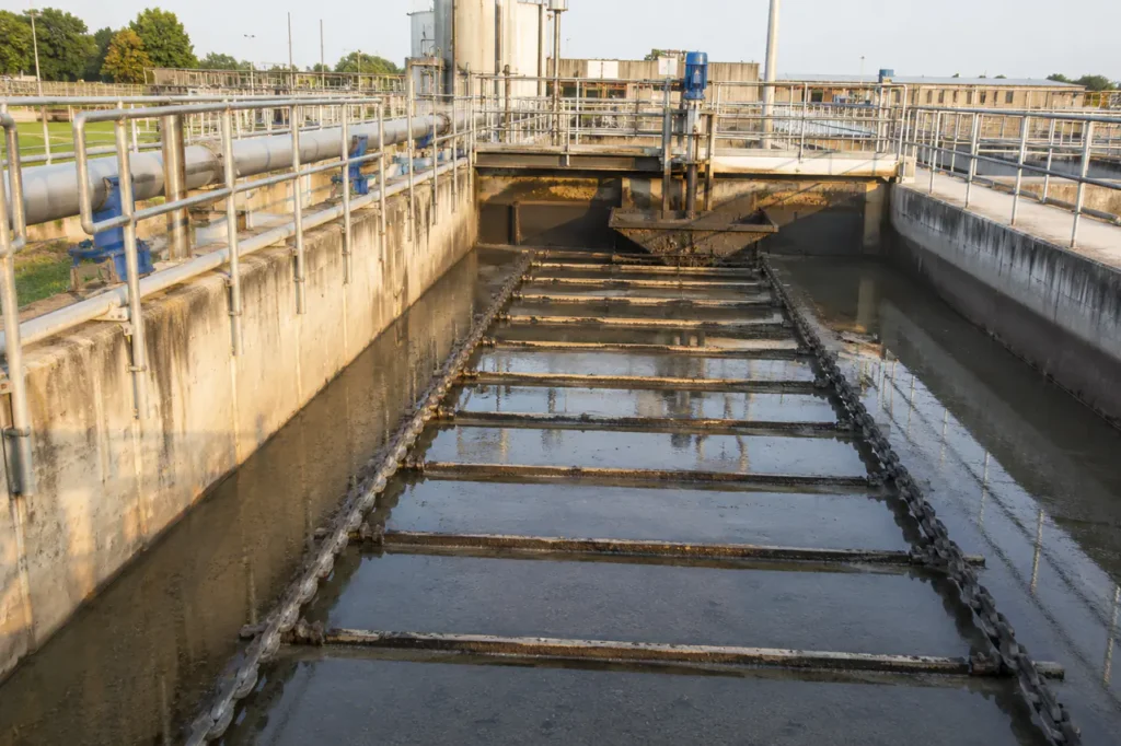
Chain and flight scrapers use two continuous strands of submerged chain connected by parallel scrapers across flat-bottomed rectangular basins. The endless chain drags settled sludge along the tank floor toward a collection hopper located at the inlet end.
On the return path along the water surface, the flights skim floating scum toward a scum trough. This dual action makes rectangular units an efficient choice for primary sedimentation and flotation processes.
Integrating a modular design inside a Wastewater Clarifier saves floor space in compact plant footprints.
- Collector chains run submerged along the basin floor and return above the waterline for combined sludge and scum movement.
- Parallel scraper flights keep settled sludge moving between hopper cycles without redispersing solids into the water column.
- Chain tension and sprocket alignment need scheduled inspection because they affect track wear and basin floor contact.
- Wear shoes or guide rails protect concrete slabs from metal-to-concrete abrasion in rectangular basins.
Spiral Blade Scrapers (Circular)
Spiral blade scrapers use continuous logarithmic curved blades positioned across the floor of circular settling basins. Unlike straight radial rake arms that push sludge incrementally with each revolution, a spiral blade sweeps settled solids continuously inward toward a central collection drum.
- Continuous curved blades clear the basin floor in a single 360-degree rotation without waiting for multiple rake-arm passes.
- Short floor residence time reduces denitrification and septic gas release in secondary biological clarifiers.
- Rapid removal suits high-sludge-volume-index activated sludge that tends to float if retained too long.
Radial and Central Drive Scrapers (Circular)
Central drive scrapers feature a rotating drive shaft or cage mounted to a central pier or overhead bridge. Two or four radial rake arms fitted with angled squeegees push settled sludge along a sloped floor into a central sludge well.
For large circular basins exceeding 30 meters in diameter, peripheral drive designs use a traction bridge powered by a drive wheel running along the outer concrete wall. This setup delivers reliable torque distribution when operating a Clarifier For Industrial Wastewater handling heavy inorganic solids.
- Specify central drive for 5-30 m basins where a central pier carries the drive torque economically.
- Use peripheral drive above 30 m when reducing structural load on the basin center improves hydraulics.
- Check rake-arm tip speed and floor slope because both affect whether heavy grit moves toward the sludge pocket.
Application Comparison and Tank Compatibility
Tank geometry directly affects hydraulic distribution, floor surface area, and civil construction expenses. Matching scraper geometry to tank shape ensures reliable sludge removal from clarifiers without dead zones or fluid short-circuiting.
| Scraper Mechanism | Tank Geometry | Optimal Scale / Diameter | Typical Wastewater Applications |
|---|---|---|---|
| Chain & Flight System | Rectangular | Length: 10-60 m, Width: 3-10 m | Space-constrained municipal plants, primary settling, heavy grease and scum removal. |
| Spiral Blade Scraper | Circular | Diameter: 6-45 m | Secondary biological clarifiers, activated sludge plants, applications needing rapid sludge removal. |
| Central Drive Rake | Circular | Diameter: 5-30 m | Primary sedimentation, industrial process water clarification, heavy inorganic sludge settling. |
| Peripheral Drive Scraper | Circular | Diameter: 25-60+ m | Large municipal wastewater facilities, high-volume secondary clarification, wide basin footprints. |
Rectangular vs Circular Decision Points
- Rectangular chain-and-flight layouts can cut site footprint by 20 to 30 percent through shared wall construction.
- Submerged moving parts in rectangular basins require scheduled dewatering for chain, sprocket, and shoe inspection.
- Circular scraper drives keep the main gearbox and drive bearings above the waterline for simpler inspection.
- Evaluate Hydraulic Loading Rate Clarifier parameters and High Rate Clarifier layouts before locking tank geometry.
Use the table above to shortlist mechanisms, then verify the hydraulic and maintenance trade-offs with your civil engineer.
Drive Units and Engineering Standards
Drive assemblies operate continuously under high torque loads and wet ambient conditions. Mechanical drive failure leads to uncollected sludge accumulation, septic effluent conditions, and costly emergency plant shutdowns.
Torque Controls and Overload Protection
Heavy sludge blankets, sudden solids spikes, or foreign debris on the basin floor cause sharp increases in drive torque. Mechanical overload protection relies on calibrated shear pin couplings that break at set torque thresholds, physically disengaging the drive motor.
- Mechanical shear pins release at a calibrated threshold to disengage the drive before gearbox damage occurs.
- Electronic torque monitoring tracks motor current and alarms near 120 percent of nominal torque.
- Shutdown protection trips around 150 percent to protect drive shafts, rake arms, and concrete basin fittings.
AGMA Standards and Lubrication
Gear reducers should be specified according to AGMA (American Gear Manufacturers Association) standards, incorporating a minimum service factor of 1.25 to 1.50 for continuous 24/7 duty. Heavy cast iron gear housings protect precision planetary or worm gearing against external humidity.
- Specify AGMA-rated reducers with a service factor of 1.25 to 1.50 for continuous clarifier duty.
- Use cast iron or heavy-duty gear housings in humid clarifier galleries.
- Require oil-bath lubrication with synthetic gear oil, sight glasses, and drain ports for nonstop service checks.
Material Specifications for Aggressive Environments
Submerged components face corrosive wastewater, abrasive grit, chemical coagulants, and biological hydrogen sulfide gas. Selecting appropriate metallurgy and non-metallic polymers extends equipment service life and lowers life-cycle costs.
| Component | Standard Material | Aggressive Environment Upgrade | Maintenance Profile / Lifespan |
|---|---|---|---|
| Scraper Flights / Blades | Coated carbon steel / FRP | 304 / 316 Stainless steel | 10-15 year lifespan; minimal corrosion risk with synthetic materials. |
| Collector Chains | Malleable cast iron | Non-metallic polymeric (Nylon/Acetal) | Eliminates pin corrosion; reduces drive power requirement by 40%. |
| Drive Shafts & Sprockets | Cast iron sprockets, steel shaft | SS316 shaft, UHMWPE tooth inserts | High wear resistance; tooth inserts replaceable without sprocket removal. |
| Underwater Wear Shoes | Hardened tool steel | Ultra-High Molecular Weight PE | Self-lubricating surface prevents concrete floor gouging. |
| Hardware & Anchors | Galvanized steel | Grade 316 Stainless steel | Prevents thread seizing during maintenance overhauls. |
Non-metallic components have transformed rectangular scraper design. Polymeric chains and fiberglass flights resist chemical corrosion and weigh up to 70 percent less than traditional cast iron assemblies.
- Verify chloride and pH ranges before choosing stainless steel; high-chloride service may require 316L or duplex steel.
- Check sulfide levels in enclosed basins because hydrogen sulfide attacks cast iron chains and fasteners.
- Use non-metallic chains and wear shoes when basin dewatering is infrequent or concrete floor protection is critical.
- Compare component weight and drive power savings when replacing cast iron flights with FRP blades.
Lower component mass reduces drive motor power consumption and minimizes mechanical strain on drive sprockets. Combining non-metallic scrapers with proper Wastewater Sludge Treatment standards improves uptime in both industrial and municipal Activated Sludge Wastewater Treatment processes.
Sludge Scraper Selection Criteria Checklist
Selecting an optimal scraper mechanism requires auditing physical, biological, and mechanical variables before finalizing plant drawings.
- Sludge Rheology and Density: Heavy inorganic grit and chemical precipitates require high-torque central drive rakes. Light organic flocs fit rapid-removal spiral scrapers.
- Sludge Volume Index (SVI): High SVI biological sludges settle slowly. Spiral scrapers or suction header designs rapidly draw off sludge before denitrification causes solids to float.
- Hydraulic Overflow Rate: Verify that floor scraping speeds (typically 0.3 to 1.2 meters per minute) do not scour settled sludge back into the clear effluent zone.
- Surface Scum Handling: Rectangular chain systems carry scum to surface troughs automatically. Circular clarifiers require dedicated surface skimmer arms and scum beaches.
- Basin Floor Tolerances: Rigid scraper blades require smooth grout floors. Wheeled scraper carriages or flexible squeegees accommodate minor concrete floor unevenness.
- Pre-treatment Comparison: Verify if gravity settling matches your solids load or if a Daf Vs Clarifier evaluation is required for light, oily solids.
- Separation Requirements: Review overall process needs using established Clarifiers And Separators selection rules before approving civil drawings.
Preparing Your Specifications for Custom Sizing
Sizing a sludge scraper system requires gathering site operational data and physical basin parameters. Providing complete process parameters helps application engineers calculate drive torque ratings, tip speeds, and structural load profiles.
- Design flow rates: average daily flow, peak hourly flow, and minimum seasonal flow (m3/day or GPM).
- Influent suspended solids (TSS) concentration and anticipated sludge generation rates (kg TSS/day).
- Basin geometry: existing or planned length, width, sidewater depth, or circular tank diameter.
- Wastewater characteristics: fluid temperature range, pH levels, chloride levels, and chemical coagulant dosing rates.
- Electrical and drive specifications: voltage, phase, motor efficiency class, and hazardous area classification.
WCT application specialists evaluate process settling rates, mechanical torque margins, and basin layout constraints to match your site needs. Submit your process data and basin drawings for a custom torque and sizing review.