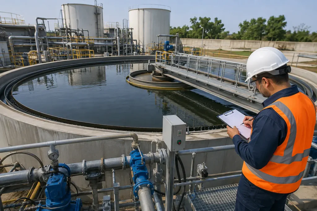
Plant upgrades often face rigid site boundaries, fluctuating influent turbidity, and strict discharge limits. Integrating a modern high rate clarifier allows industrial facilities and municipal plants to expand hydraulic capacity without committing to new civil works or acquiring additional real estate.
The Engineering Case: High-Rate vs. Conventional Clarification
High-rate clarifiers achieve surface loading rates 4 to 8 times higher than conventional gravity settling tanks.
By operating at rise rates from 5 to over 15 gpm/sq.ft (12 to 36 m/h) compared to standard gravity sedimentation rates of 0.5 to 1.5 gpm/sq.ft, these compact systems drastically reduce footprint requirements.
Conventional settling relies strictly on Stokes’ Law, where discrete or flocculent particles settle under natural gravity inside large concrete basins.
This requires long hydraulic retention times (typically 2 to 4 hours) and large surface areas. In contrast, high-rate clarification modifies particle settling velocity by adding ballast, injecting microbubbles, or utilizing inclined plate/tube settler geometry.
Evaluating an upgrade involves balancing footprint reduction against operational trade-offs. While conventional basins require minimal chemical dosing and low operator intervention, high-rate units require precise coagulation, automated polymer feed, and continuous solids management.
Understanding how these operational parameters shift is essential when evaluating a Hydraulic Loading Rate Clarifier or replacing an aging Circular Clarifier Water Treatment basin.
| Performance Parameter | Conventional Gravity Clarifier | Lamella Plate / Tube Settler | Microsand Ballasted Flocculation | High-Rate Dissolved Air Flotation (DAF) | High-Rate Solids-Contact Thickener |
|---|---|---|---|---|---|
| Surface Overflow Rate (gpm/sq.ft) | 0.5 – 1.2 | 2.0 – 4.0 | 15.0 – 30.0 | 8.0 – 15.0 | 4.0 – 8.0 |
| Hydraulic Retention Time (min) | 120 – 240 | 45 – 60 | 10 – 15 | 10 – 20 | 60 – 90 |
| Footprint Relative to Conventional | 100% (Baseline) | 25% – 40% | 5% – 15% | 10% – 20% | 20% – 30% |
| Effluent Turbidity Target (NTU) | 2.0 – 10.0 | 1.0 – 5.0 | < 0.5 | < 1.0 | 1.0 – 5.0 |
| Chemical Conditioning Needs | Low (Basic Coagulation) | Moderate | High (Coagulant + Polymer) | Moderate to High | Moderate (Lime/Polymers) |
| Mechanical & Control Complexity | Low | Low to Moderate | High (Hydrocyclone loop) | High (Saturator & Skimmer) | Moderate (Recirculation Drive) |
The choice between these systems hinges on raw water characteristics. High overflow rates reduce civil costs but increase reliance on automatic chemical dosing, energy input, and sludge handling equipment.
Core High-Rate Clarifier Technologies
High-rate clarification mechanisms fall into three primary engineering architectures. Each solves a specific settling velocity constraint using a distinct mechanical and physical method.
Microsand Ballasted Flocculation
Microsand ballasted flocculation introduces micro-sand (100 to 150 microns, specific gravity ~2.65) alongside coagulant and high-molecular-weight polymer into rapid-mix tanks. The microsand acts as a heavy carrier nucleus, binding with suspended solids to create dense micro-flocs.
These ballasted flocs enter a lamella settling zone with settling velocities exceeding 40 m/h. The heavy solids drop out rapidly into an underflow hopper.
Sludge is pumped to a hydrocyclone manifold that separates the sand from the concentrated waste sludge, recycling the sand continuously back to the mix tank.
This process offers short retention times (under 15 minutes) and handles raw water turbidity spikes from 20 NTU to over 1,500 NTU without losing effluent quality.
Operators must monitor hydrocyclone liner wear, sand pump erosion, and ensure consistent polymer dosing to prevent sand carryover into downstream filters.
Dissolved Air Flotation (DAF)
Dissolved Air Flotation reverses traditional gravity settling by using air as the separation medium. High-pressure recycle streams (4 to 6 bar) saturated with air are depressurized into the flotation zone through special nozzle headers, generating dense clouds of microbubbles (30 to 50 microns).
These bubbles attach to chemical flocs, creating a buoyant composite with a low effective specific gravity. The floated sludge forms a heavy blanket on the surface, which is removed continuously by zero-speed mechanical skimmers, while clarified effluent flows out through bottom discharge launders.
High-rate DAF systems excel at removing low-density suspended solids, light organic matter, oil/grease, and seasonal algae blooms. Evaluating DAF Vs Clarifier options reveals that DAF delivers superior performance when treating low-turbidity, highly colored surface waters that generate light, float-resistant flocs.
High-Rate Sludge Thickeners (Solids Contact)
High-rate solids-contact thickeners combine chemical reaction, flocculation, clarification, and sludge compaction inside a single vessel. A central draft tube with an internal variable-speed impeller recirculates pre-formed sludge solids back into incoming raw water at ratios up to 4:1.
This recirculation increases particle collision frequency, forming dense, self-filtering sludge blankets. Heavy solids settle into a bottom compaction zone equipped with dual-arm rake mechanisms, yielding underflow solids concentrations up to 3% to 10% dry weight.
By producing concentrated sludge directly from the clarifier underflow, facilities eliminate the capital and footprint requirements of a separate gravity thickener tank. This makes solids-contact units preferred for heavy precipitation, lime softening, and FGD wastewater treatment.
Application Match Matrix: Selecting the Right System
Matching process conditions to the correct technology prevents common startup failures, such as premature plate fouling, chemical overdosing, or high carryover turbidity.
| Technology Type | Ideal Influent Characteristics | Typical Influent Limits | Target Effluent Quality | Key Process Limitation |
|---|---|---|---|---|
| Microsand Ballasted Flocculation | High TSS variability, rapid turbidity spikes, cold water municipal intakes | TSS: 50 – 2,000+ mg/L Turbidity: Up to 3,000 NTU |
Turbidity < 0.5 NTU TSS < 5 mg/L |
Requires continuous polymer feed; mechanical wear on sand recycle pumps |
| High-Rate Dissolved Air Flotation | Algae blooms, low-density organic flocs, oil/grease, high TOC/color | TSS: 20 – 500 mg/L Oil/Grease: < 100 mg/L |
Turbidity < 1.0 NTU TSS < 10 mg/L |
Ineffective for heavy inorganic sand/grit; requires high recycle energy |
| Solids Contact / High-Rate Thickener | Lime softening, heavy metal precipitation, scale control, mining run-off | TSS: 500 – 10,000+ mg/L Hardness / Heavy Metals |
Turbidity < 5.0 NTU Underflow: 3 – 10% Solids |
Requires steady feed rate; sensitive to sudden hydraulic surges |
| Lamella / Tube Settler Basin | Low-to-moderate inorganic TSS, secondary municipal clarifier upgrades | TSS: 50 – 500 mg/L Turbidity < 300 NTU |
Turbidity < 2.0 NTU TSS < 15 mg/L |
Plates foul if sludge is sticky; delicate hydraulic distribution required |
Municipal Drinking Water & Surface Water
Municipal surface water treatment plants must comply with strict drinking water mandates, including the Long Term 1 Enhanced Surface Water Treatment Rule (LT1ESWTR). These regulations mandate multi-barriers against pathogen passage, requiring consistent clarifier effluent turbidity below 0.5 NTU prior to media filtration.
When selecting a municipal Water Treatment Plant Clarifier, ballasted flocculation provides a robust barrier against flash floods and cold-water settling slowdowns. Rapid particle aggregation allows plants to maintain high MGD production despite sudden shifts in river turbidity without risking filter blinding.
Algae & Low-Density Solids Removal
Reservoirs and open water bodies frequently experience seasonal algae blooms. Cyanobacteria and organic natural matter have low specific gravity, causing them to float or stay suspended in conventional gravity settlers, which leads to rapid filter clogging and taste/odor issues.
High-rate DAF systems achieve 90% to 99% algae cell removal by floating cells using microbubbles. Removing algae intact prevents cell rupture, preventing the release of intracellular toxins and taste-and-odor compounds (MIB and Geosmin) into the process stream.
High-Velocity Industrial Wastewater
Heavy manufacturing, mining, metal finishing, and power generation produce dense industrial wastewater containing heavy metals, sulfates, and mineral scaling compounds. These streams require precipitating dissolved contaminants into dense suspended solids.
In heavy industrial applications, combining an Industrial Water Recycling Solution Vs Traditional Treatment Comparison highlights the advantages of high-rate thickeners over standard settling.
Facilities operating a dedicated Wastewater Clarifier or a specialized Clarifier Water Treatment system can achieve combined chemical neutralization, clarification, and sludge dewatering in a single compact process train.
Critical Design Parameters and Operational Variables
Successful execution relies on specifying hydraulic, chemical, and mechanical integration variables accurately during early engineering design.
Surface Loading and Rise Rates
The effective surface area of a high-rate unit determines its hydraulic ceiling. For lamella plate settlers, projected horizontal surface area is calculated using plate angle, length, and spacing:
Aeff = Afootprint × (1 + n × cos(θ))
Where n represents the number of stacked plates and θ is the angle of inclination (typically 55 to 60 degrees).
Maintaining laminar flow between plates requires keeping the Reynolds number (Re) below 500 and the Froude number (Fr) above 10-5 to prevent internal short-circuiting and re-entrainment of settled solids.
Chemical Conditioning and Polymer Selection
High-rate clarification relies heavily on chemical reaction kinetics. Without optimal coagulant and polymer dosing, micro-flocs will shear under high velocity, destroying clarification efficiency.
- Primary Coagulation: Aluminum sulfate, polyaluminum chloride (PAC), or ferric chloride neutralizes negative surface charges, promoting initial pin-floc formation in rapid mixing zones (G-value: 500 to 1,000 s-1).
- Flocculation Bridging: High-molecular-weight anionic or cationic polymers are added in secondary slow-mix zones (G-value: 50 to 100 s-1) to form large, shear-resistant flocs.
- Dosing Control: Automated streaming current monitors and online turbidity feedback adjust chemical dosing continuously to prevent chemical wasted from under- or over-dosing.
Footprint Optimization & Retrofit Considerations
Upgrading existing water facilities rarely provides open space for new civil construction. Retrofitting existing concrete basins with high-rate internal hardware is an economical way to increase plant MGD capacity within the current layout.
Engineers can replace worn rake mechanisms in existing rectangular or circular basins with stainless steel lamella plate packs or high-rate DAF headers. This conversion quadruples plant treatment capacity without adding new basin walls, saving substantial civil capital expenditure.
Upgrading feed and sludge lines requires matching head loss profile requirements. Installing robust feed pumps, like the Wct Cdlfcdh High Pressure Pump For Waste Water Treatment, ensures reliable flow distribution across internal manifolds and maintains steady saturation pressures in high-rate air-dissolution loops.
System Integration and Pilot Testing Requirements
Because high-rate clarifiers operate with short hydraulic retention times, they are sensitive to changes in raw water quality and chemical dosing errors. Jar testing and pilot skid demonstrations are essential pre-specification steps to establish precise operating parameters before full-scale purchase.
Gather the following operational baseline data before finalizing system dimensions or specifying process guarantees:
- Raw Water Quality Range: Collect historical minimum, average, and peak records for water temperature, pH, conductivity, TSS, total organic carbon (TOC), and seasonal turbidity spikes.
- Bench-Scale Jar Testing: Run jar tests using site water to determine optimal coagulant types, dosing rates, pH setpoints, polymer types, and pin-floc settling speeds.
- Hydraulic Boundary Conditions: Establish minimum, design, and peak hourly flow rates (MGD or m3/h), available gravity head, and downstream elevation limits.
- Sludge Dewatering Targets: Define underflow solids concentration targets, daily sludge production volumes, and disposal requirements for downstream filter presses or centrifuges.
- Pilot Skid Evaluation: Run a mobile, containerized high-rate pilot unit on-site for 2 to 4 weeks during challenging raw water conditions (such as seasonal algae blooms or flood conditions) to verify real-world surface loading limits.
When expanding plant capacity or addressing tight footprint constraints, specifying a high rate clarifier requires close coordination between site process engineers and equipment manufacturers.
Before finalizing equipment schedules, verify your site’s raw water characterization curves and review jar testing protocol specs.
Contact our engineering team at WCT to review raw water data, model treatment kinetics, arrange pilot skid testing, or request custom process integration brochures tailored to your facility.