Most water quality specifications start with a general purity target. An ultrapure water treatment system starts with two hard numbers: 18.2 MΩ·cm resistivity and less than 5 ppb total organic carbon. If your application does not need both thresholds, a Type 2 system may be the better investment.
Defining Ultrapure Water (Type 1 Standards and Parameters)
Type 1 ultrapure water is not simply highly filtered water. It is defined by its maximum theoretical electrical resistivity and near-zero organic and particulate content. The 18.2 MΩ·cm benchmark represents the resistivity of pure water at 25°C – any measurable drop in resistivity signals ionic contamination.
An industrial water purifier configured for Type 1 output must simultaneously meet multiple parameter limits. Resistivity alone tells only half the story. TOC, bacteria, and endotoxin levels separate true ultrapure water from standard deionized water.
| Parameter | Type 1 (Ultrapure) | Type 2 (Pure) | Type 3 (Primary Grade) |
|---|---|---|---|
| Resistivity (MΩ·cm, 25°C) | > 18.0 | > 1.0 | > 0.05 |
| Conductivity (µS/cm) | < 0.056 | < 1.0 | < 20 |
| TOC (ppb) | < 5 | < 50 | < 200 |
| Bacteria (CFU/ml) | < 1 | < 100 | < 1000 |
| Endotoxins (EU/ml) | < 0.03 | N/A | N/A |
Resistivity is the primary metric for ionic purity because it responds immediately to dissolved salts and ionized species. TOC measures organic carbon from natural matter, bacterial byproducts, or leachables from system components. Both must be monitored continuously – not just at commissioning.
Three standards govern Type 1 water quality: ASTM D1193 (Type I), ISO 3696 (Grade 1), and CLSI-CLRW guidelines for clinical laboratories. Each sets slightly different limits, but all converge on the 18.2 MΩ·cm resistivity and low-TOC requirements.
The Three-Stage System Architecture
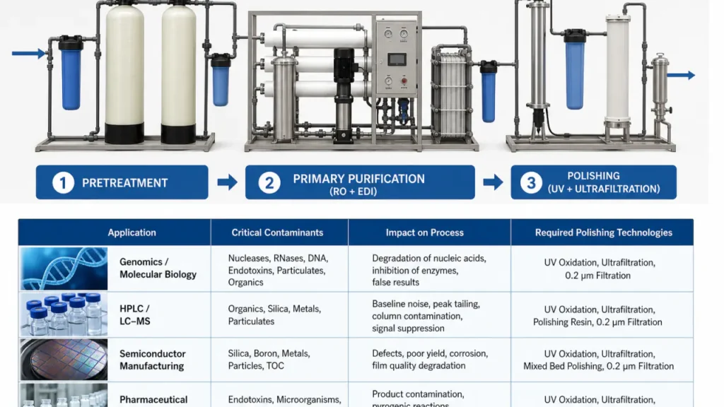
A single filter cannot produce ultrapure water from tap feed. A properly designed ultrapure water treatment system uses three sequential stages to remove different contaminant classes in order of size and difficulty. Skipping or undersizing any stage shifts the burden downstream and shortens consumable life.
Stage 1: Pretreatment (Protecting the Core)
Pretreatment removes the contaminants that damage expensive primary-stage components. The main targets are chlorine, hardness minerals, suspended solids, and large organic molecules. Without adequate pretreatment, RO membranes foul quickly and EDI stacks scale up.
Standard pretreatment includes:
- Activated carbon filtration to strip free chlorine and chloramine
- Water softening or antiscalant dosing to control hardness
- Depth or multi-media filtration to remove suspended particles above 5-10 µm
- Optional iron and manganese removal for well-water sources
Pretreatment options for ultrapure water vary significantly based on feed water chemistry. Municipal water in different regions carries different chlorine levels and hardness profiles. A feed water analysis is not optional – it determines the pretreatment design.
Stage 2: Primary Purification (Bulk Deionization)
Primary purification removes 95-99% of total dissolved solids. Reverse osmosis systems form the backbone of this stage, followed by electrodeionization (EDI) for final salt removal without chemical regeneration.
RO membranes reject dissolved ions, silica, organics, and bacteria based on size and charge. Performance varies with feed pressure, temperature, and membrane condition:
- Single-pass RO typically reduces conductivity to 5-20 µS/cm.
- Double-pass RO pushes conductivity closer to 1 µS/cm, providing excellent feed for EDI.
- Key contaminants removed: Na⁺, Ca²⁺, Cl⁻, silica (SiO₂), organic molecules >200 Da, bacteria, and viruses.
EDI combines ion-exchange membranes with electric current to continuously remove residual ions. Unlike mixed-bed deionization tanks, EDI does not require acid and caustic regeneration on site. This eliminates chemical handling and reduces downtime between exchanges. EDI output typically reaches 10-15 MΩ·cm before entering the polishing stage.
Stage 3: Polishing (Achieving 18.2 MΩ·cm)
The polishing stage takes deionized water from EDI output to the final 18.2 MΩ·cm benchmark. This stage removes trace ions, organic carbon, bacteria, and endotoxins that survived primary treatment.
Three technologies work in series during polishing:
- Mixed-bed ion-exchange resin for final ionic removal to reach 18.2 MΩ·cm
- UV photo-oxidation polishing at 185 nm to break down residual TOC below 5 ppb
- 254 nm UV for bacteria and microbial inactivation
- Ultrafiltration modules with 5-10 kDa molecular weight cutoff to remove endotoxins and nucleases
The cost of getting from 15 MΩ·cm to 18.2 MΩ·cm is substantial. It requires tight control of dissolved CO₂, high-purity polishing resin, and short residence times in the distribution loop to prevent re-contamination.
Application-Specific System Requirements
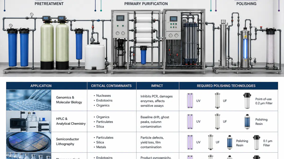
The exact polishing configuration depends on which contaminant matters most in your process. A genomics lab and a semiconductor fab both need 18.2 MΩ·cm water, but their system architectures diverge at the polishing stage.
| Application | Critical Contaminant | Required Polishing Technology |
|---|---|---|
| Genomics / PCR | Nucleases (RNase/DNase) | UF hollow fiber + 185 nm UV |
| HPLC / LC-MS | Organic carbon (TOC) | 185/254 nm UV + low-TOC IX resin |
| Cell Culture / IVF | Endotoxins, pyrogens | UF (5 kDa) + sterile-grade filtration |
| Semiconductor Lithography | Silica, boron, nanoparticles | UF + degasification + 185 nm UV |
| Pharmaceutical Manufacturing | Endotoxins, bacteria, TOC | UF + UV + IQ/OQ/PQ documentation |
Laboratory and Life Sciences
Life science applications demand water free of nucleases, proteases, and endotoxins. A standard 18.2 MΩ·cm system without ultrafiltration may pass resistivity and TOC checks but still ruin a PCR assay or cell culture batch.
For HPLC and trace analysis, TOC is the primary concern. Organic contaminants create ghost peaks and shift baselines. Pharmaceutical water treatment for analytical labs typically requires dual-wavelength UV oxidation – 185 nm to break down organics and 254 nm to sterilize.
Common lab UPW polishing configurations:
- Genomics/PCR: UF with 5 kDa cutoff plus 185 nm UV to destroy nucleases.
- HPLC/LC-MS: 185/254 nm UV oxidation and low-TOC ion-exchange resin, targeting TOC <3 ppb.
- Cell culture/IVF: UF, sterile-grade final filtration, and endotoxin validation per USP <85>.
Semiconductor and Microelectronics
Ultrapure water for semiconductor lithography pushes purity requirements beyond laboratory standards. Wafer fabrication at sub-10 nm nodes cannot tolerate any particle above 20-50 nm, any trace of silica, or boron leaching from ion-exchange resin.
Semiconductor UPW systems add degasification membranes to remove dissolved oxygen and CO₂. They also use high-purity boron-free polishing resin. The distribution loop design – material selection, velocity, dead-leg elimination – becomes as critical as the treatment equipment itself.
Typical semiconductor-grade UPW requirements:
- Particle count: < 100 particles/L > 50 nm for advanced nodes.
- Silica: often below 0.5 ppb to prevent crystal defects.
- Boron: below 0.05 ppb using boron-specific ion-exchange resin.
- Dissolved oxygen: < 1 ppb via membrane contactors to avoid silicon oxidation.
Pharmaceutical Manufacturing
Pharmaceutical-grade UPW must meet pharmacopeia standards for water for injection (WFI) or purified water. Beyond the chemical parameters, the system must include validation documentation: Installation Qualification (IQ), Operational Qualification (OQ), and Performance Qualification (PQ).
Regulatory inspectors will review the entire purification train, monitoring records, and sanitization logs. A system that produces 18.2 MΩ·cm water without the corresponding documentation package will fail a GMP audit.
Essential validation and compliance elements:
- IQ/OQ/PQ protocol documents with defined acceptance criteria.
- Continuous online monitoring and data logging for resistivity, TOC, flow, and temperature.
- Sanitization cycles (hot water, ozone, or chemical) with supporting SOPs.
- Sterile filtration and endotoxin testing per USP <85> or equivalent.
System Sizing, Monitoring, and Maintenance
Getting the purification architecture right solves only half the problem. The system must deliver the required volume at the right flow rate, with continuous quality verification, and without excessive consumable costs.
Capacity and Flow Rate Planning
There is a practical difference between daily production capacity and peak dispense rate. A system rated at 100 L/day may produce 4 L/hr continuously, but a busy lab bench may need 2 L/min dispense for filling containers and rinsing glassware.
Size the primary stage for daily volume and the polishing loop for peak demand. Under-sizing either creates bottlenecks. A common mistake is sizing only for average daily consumption and ignoring the morning rush when multiple analysts dispense simultaneously.
Key sizing steps:
- Calculate total daily volume (L), adding a 20% safety margin for future growth.
- Determine peak simultaneous demand (L/min) based on number of draw-off points.
- Ensure the primary purification stage can recover during off-peak hours to refill storage.
- Check that the recirculation loop velocity stays above 0.9 m/s to maintain flow quality.
Inline Quality Monitoring
Spot testing water quality from a sample port gives a single data point – not a process record. Inline monitors provide continuous resistivity and TOC readings at the polishing outlet and at critical use points.
Temperature-compensated resistivity sensors are essential. Raw resistivity changes with temperature, and uncompensated readings at 18°C versus 25°C can show a false pass or false fail. Inline TOC analyzers using UV-persulfate oxidation give real-time organic carbon data at the 1-ppb detection level.
Minimum inline monitoring package for UPW systems:
- Resistivity/conductivity sensor with automatic temperature compensation at point of use.
- Online TOC analyzer with detection limit ≤ 1 ppb, preferably with alarm on drift.
- Flow-rate meter to track dispense volume and loop velocity.
- Optional particle counter for semiconductor applications requiring nanoparticle control.
Consumable Replacement Cycles
Pretreatment cartridges, UV lamps, polishing resin, and ultrafiltration modules all have finite service lives. Replacement frequency depends on feed water quality, daily throughput, and how close to the contaminant breakthrough point the operator runs the system.
Replacing consumables on time prevents downstream damage. Running exhausted carbon cartridges sends chlorine to the RO membranes. Running depleted polishing resin drops resistivity and pushes silica into the product water. A maintenance log with consumption tracking lowers the total cost of ownership more than pushing cartridge life to its limit.
Typical service intervals (subject to water quality):
- Pretreatment carbon/softener: 6-12 months, depending on chlorine and hardness load.
- RO membranes: 2-4 years with proper antiscalant and cleaning.
- EDI stacks: Often 5+ years, with periodic chemical cleaning.
- 185 nm UV lamps: Replace annually to maintain TOC oxidation efficiency.
- Polishing resin: 6-12 months in high-use labs; exchange when resistivity drifts below 18.0 MΩ·cm.
- UF modules: 2-3 years, or sooner if permeate flow drops >15%.
Warning signs of exhausted consumables:
- Conductivity creep in RO permeate → membrane scaling or fouled pretreatment.
- Pressure drop increase across UF → fouling or particle loading.
- TOC spike at system outlet → exhausted carbon or aging UV lamp.
- Endotoxin detection → bypassed or failed ultrafiltration.
What to Verify Before Requesting a System Quote
An accurate system configuration and price starts with information the vendor cannot guess. Prepare these data points before reaching out to engineering teams. Missing information leads to oversized systems, undersized pretreatment, or quotes that do not match the actual installation site.
- Feed water source and chemistry: Municipal tap, pre-treated RO permeate, or distilled? Include a recent water analysis with conductivity, TDS, hardness, chlorine, iron, and silica values.
- Daily volume demand: Total liters per day the lab or facility actually consumes, not theoretical capacity. Include peak-hour dispense rate in L/min.
- Required water quality: Confirm Type 1 per ASTM D1193. Specify if you need endotoxin-free or nuclease-free water for life science applications.
- Validation documentation: Does the facility operate under GMP, GLP, or ISO 17025? IQ/OQ/PQ documentation packages add cost but are non-negotiable in regulated environments.
- Installation constraints: Benchtop, under-bench, wall-mounted, or centralized loop? Available floor space, drain access, and electrical supply determine which configurations are feasible.
- Distribution method: Point-of-use dispenser at a single bench, or a recirculating loop serving multiple floors and laboratories? Loop design requires attention to pipe material, velocity, and dead-leg prevention.
- Existing pretreatment: Does the facility already have softened or carbon-filtered water? Reusing existing pretreatment can reduce capital cost but must be verified for UPW duty.
- Vendor support expectations: On-site commissioning and training requirements, preventive maintenance contract interest, and remote monitoring needs.
Skipping the feed water analysis is the single most expensive mistake in UPW procurement. A system specified without knowing the feed conductivity and chlorine level will either underperform or consume consumables at twice the expected rate.
Engineering Consultation and System Specification
Specifying an ultrapure water treatment system requires matching the purification train to your feed water chemistry, daily volume, and end-use purity requirements. Off-the-shelf configurations exist, but most facilities benefit from a sizing review that accounts for local water quality and peak demand.
At WCT, our engineering team works from your feed water analysis and demand profile to configure the pretreatment, primary, and polishing stages as a single integrated system. We can review legacy system performance, identify bottlenecks, and specify a replacement that fits within existing space and utility constraints.
To request a system specification or sizing review, have your feed water analysis, daily volume estimate, and quality requirements ready. Custom ultrapure water systems configured to actual site conditions cost less to operate than oversized standard packages that were specified from assumptions.
Frequently Asked Questions
Can an ultrapure water system run directly on municipal tap water?
It depends on the system type. Fully integrated UPW systems include built-in pretreatment cartridges designed for tap water feed. Polishing-only units – often benchtop models – require Type 2 or RO-quality feed water. Always check the manufacturer’s required feed water specification. Feeding tap water to a polishing-only system will exhaust the polishing cartridges within hours, not months.
What is the difference between resistivity and TOC in UPW?
Resistivity measures ionic contamination – dissolved salts, acids, and bases that dissociate in water and carry an electrical charge. TOC measures organic carbon from natural organic matter, biological byproducts, or plasticizer leaching. They are independent parameters. Water can read 18.2 MΩ·cm and still contain 50 ppb TOC if the organic contaminants are non-ionic. Both must be monitored separately.
Why can’t ultrapure water be stored for long periods?
Ultrapure water is a highly aggressive solvent. Left in a storage tank, it rapidly absorbs carbon dioxide from the air, forming carbonic acid and dropping resistivity below 1 MΩ·cm within hours. It also leaches trace ions and organic compounds from container materials. The best practice is continuous recirculation through a polishing loop, not static storage.