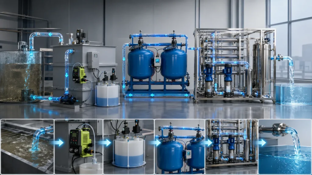
In industrial manufacturing, the quality of process water is rarely a secondary concern. A misstep in treatment can cause scaling in heat exchangers, defective surface finishes, or non-compliance with process water treatment system discharge permits. The technical reality is that there is no universal design—only a system engineered to match specific feed water chemistry and end-use purity targets.
What follows is a practical engineering guide that breaks down water treatment stages, compares core purification technologies, and maps industry-specific quality parameters. Plant managers and process engineers can use this to align system design with operational demands, not just theoretical best practices.
Process Water vs. Potable Water: Defining the Industrial Scope
Process water is formulated for industrial tasks—rinsing, cooling, plating, boiler feed—where specifications for conductivity, silica, and TDS outweigh potable water health standards. Potable water must meet human consumption limits; process water must guarantee production consistency and equipment protection. A process water treatment system is built around target quality parameters that municipal supplies rarely deliver without additional polishing.
Feed water source dictates the starting point. Well water may carry high iron and hardness; surface water introduces seasonal turbidity and organics; municipal water still contains residual chlorine that attacks RO membranes. Early feed water analysis defines whether you need simple media filtration, softening, or a multi-stage membrane train.
The 5 Essential Stages of the Process Water Treatment Cycle
Most industrial treatment trains follow a logical sequence: Coagulation, Flocculation, Sedimentation, Filtration, and Disinfection. This sequence transforms raw feed water into a clean stream suitable for downstream polishing. We refer to these as the 5 standard stages, though real-world systems may add pre-chlorination or pH adjustment depending on influent conditions.
Each stage targets a specific contaminant class, and skipping one often compromises the next. A rushed sedimentation step overloads filters; insufficient coagulation leads to colloidal carryover.
- Coagulation: Chemical coagulants (alum, ferric chloride) are dosed to neutralize surface charges on suspended particles, destabilizing colloids so they begin to aggregate. Jar testing is the standard method for optimizing dosage and pH.
- Flocculation: Gentle mixing promotes contact between destabilized particles, forming larger floc that settles more readily. Over-mixing shears the floc; under-mixing leaves fine particles in suspension.
- Sedimentation: Gravity separates floc from the water column in sedimentation tanks or clarifiers. Sludge is collected at the bottom, while clarified water overflows to the next stage. Retention time and weir loading rate are critical design parameters.
- Filtration: Remaining suspended solids pass through media filters (sand, anthracite, multimedia) or membrane screens. This stage protects downstream equipment and ensures turbidity is below membrane feed limits.
- Disinfection: UV irradiation, ozone, or chlorine dioxide control microbial growth and prevent biofouling in piping and downstream unit operations. The choice hinges on residual disinfection requirements and compatibility with membrane materials.
These stages form the backbone of an industrial water treatment process. After disinfection, the water may still require reverse osmosis or ion exchange to meet strict process requirements.
Core Technologies for Process Water Purification
Hardware selection moves beyond the basic 5-stage cycle and addresses dissolved ions, organic molecules, and micro-contaminants. The right technology depends on the target TDS, conductivity, and particle size cut-off. Understanding these options prevents oversizing or selecting membranes that foul prematurely.
The table below compares four core technologies used in process water treatment systems. Each excels in a specific contaminant removal range and energy profile.
| Technology | Primary Contaminant Removed | Energy Requirement | Typical Industrial Use Case |
|---|---|---|---|
| Reverse Osmosis (RO) | Dissolved salts, TDS, silica, heavy metals | High (pump pressure) | Boiler feed water, semiconductor rinsing, pharmaceutical purification |
| Ultrafiltration (UF) | Suspended solids, bacteria, viruses, colloids | Low to moderate | Pre-treatment for RO, food and beverage clarification, wastewater reuse |
| Ion Exchange (IX) | Hardness minerals (Ca²⁺, Mg²⁺), nitrate, selective heavy metals | Low (chemical regeneration) | Boiler softening, demineralization, metal finishing rinse water |
| Carbon Filtration | Organics, chlorine, taste and odor compounds, some VOCs | Low | Pre-RO dechlorination, beverage water polishing, groundwater remediation |
Note: Energy requirements and contaminant removal rates vary by membrane type, operating pressure, and feed water chemistry. Request performance data from the manufacturer for your specific application.
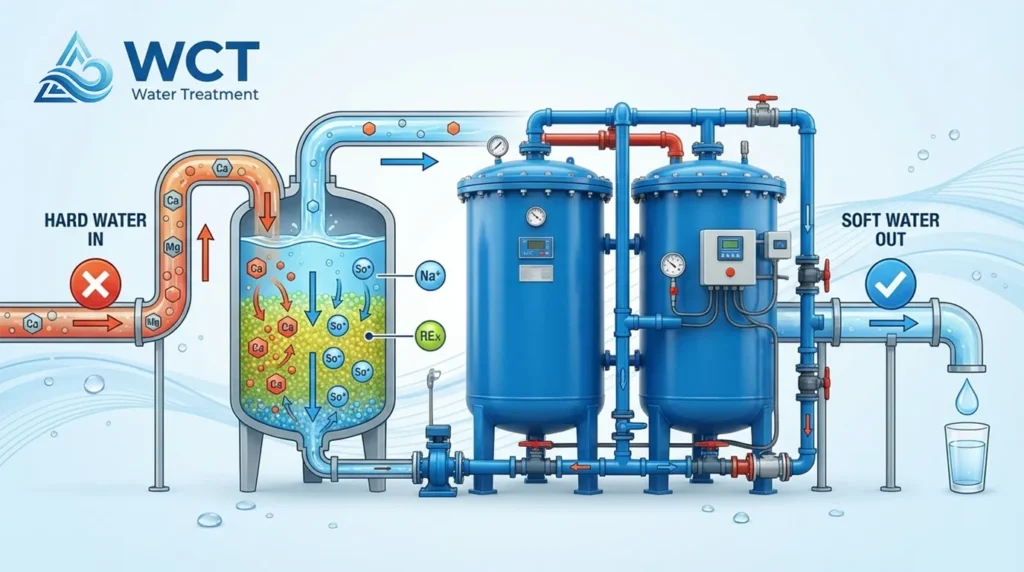
Softening deserves a separate mention. For boilers and cooling towers, scale prevention is critical. A dedicated softening system—often preceding RO—removes calcium and magnesium and dramatically extends membrane life. In many plants, a combination of softening and carbon filtration serves as the practical baseline before a process water treatment equipment membrane skid.
Industry-Specific Water Quality Requirements
Water purity is measured in orders of magnitude, not absolutes. A semiconductor fab requires resistivity in the 18.2 MΩ·cm range, while a concrete plant may only need low-turbidity process water. Designing a system without the end-use spec leads to either wasteful over-treatment or production-defect risk.
The table below outlines typical parameters by industry. These are reference points for procurement teams to map treatment stages against product quality requirements.
| Industry | Critical Parameters | Recommended Treatment Stage |
|---|---|---|
| Microelectronics/Semiconductors | TDS < 1 ppm, Resistivity > 18 MΩ·cm, Silica < 5 ppb | Two-pass RO + EDI or mixed-bed IX |
| Food & Beverage | Microbial count, Chlorine residual, TDS typically < 500 ppm | Carbon filtration + RO + UV disinfection |
| Pharmaceutical | Endotoxin levels, Conductivity < 1.3 µS/cm, TOC < 500 ppb | RO + EDI or distillation, often with ozone pre-treatment |
| Automotive/Plating | Hardness < 1 ppm, Silica control, Oil and grease removal | Softening + UF or RO, depending on rinse quality spec |
Note: The values above are typical targets. Actual requirements depend on product specifications and local regulatory standards. Verify with your process owner and equipment supplier before final design.
For facilities handling high-volume rinsing, an industrial effluent treatment loop may be integrated to recover process water and reduce discharge volumes, further tightening the water balance.
Key Engineering and Design Considerations for System Integration
System sizing is not solely about daily volume. Peak flow rates, backwash capacity, and discharge limits shape the real footprint and cost. A well-designed process water treatment system accounts for variability in feed quality and production demand.
Before specifying equipment, use this checklist to align engineering requirements with operational reality.
- Feed water analysis: Conduct a complete seasonal profile including turbidity, TDS, silica, hardness, and microbiological load. Seasonal swings in surface water temperature also affect membrane productivity.
- Flow rate and pressure requirements: Define both average and peak demand in m³/hr. Oversizing for rare peaks wastes capital; undersizing creates process bottlenecks.
- Footprint and integration: Evaluate skid-mounted versus built-in-place systems. Skid designs reduce on-site construction but require clear access for maintenance and chemical delivery.
- Regulatory compliance: Identify applicable discharge limits (EPA effluent guidelines or local municipal bylaws). Treatment trains that reduce incoming contaminant load can also reduce treatment cost at the outfall.
- Automation level: Decide whether the plant needs SCADA integration with remote monitoring, or if manual control with local gauges is sufficient. Automated systems improve consistency but require higher upfront instrumentation cost.
- Pre-treatment protection: For membrane systems, include cartridge filtration and antiscalant dosing. Neglecting pre-treatment is the most common cause of premature membrane fouling.
Before finalizing specifications, it is worth reviewing industrial water system design best practices to catch design gaps early. Also, consider whether a water recycling vs traditional treatment comparison yields a better lifecycle cost profile for your facility.
If cooling represents a large water demand, cooling water treatment parameters must be integrated into the overall water balance to avoid separate, uncoordinated systems.
Request a Custom System Audit and Technical Consultation
Every process water treatment system starts with a site-specific gap between raw water quality and target process water spec. Desktop estimates can only go so far. A technical audit that includes water analysis, flow profiling, and chemical compatibility review reduces downstream risk significantly.
Our application engineers work with plant teams to optimize treatment train selection, membrane array design, and chemical dosing schedules. We provide a downloadable technical whitepaper and system audit request to start the conversation—no obligation, just practical engineering support.
Next steps: Contact our team to discuss your feed water characteristics, production requirements, and discharge limits. We will help you determine whether a polishing RO, a full demineralization train, or a packaged UF system fits your operation best.
Frequently Asked Questions
What is the difference between ultrafiltration and reverse osmosis?
Ultrafiltration (UF) uses a physical barrier with pore sizes around 0.01-0.1 microns to remove suspended solids, bacteria, and colloids. Reverse osmosis (RO) employs a semi-permeable membrane that rejects dissolved ions and salts, operating at the molecular level. UF is a clarity step; RO is a demineralization step.
How often do process water membranes need to be replaced?
Typical membrane replacement occurs every 2-5 years, but effective pre-treatment (softening, carbon filtration, antiscalant dosing) and consistent cleaning protocols can extend this to 5-7 years. The primary causes of early replacement are fouling and oxidation damage from free chlorine.
Does process water treatment help with environmental compliance?
Yes. A properly designed system reduces contaminant load in plant effluent, helping meet local discharge permits. It also enables water reuse and recycling loops, lowering overall water withdrawal and wastewater discharge volumes.