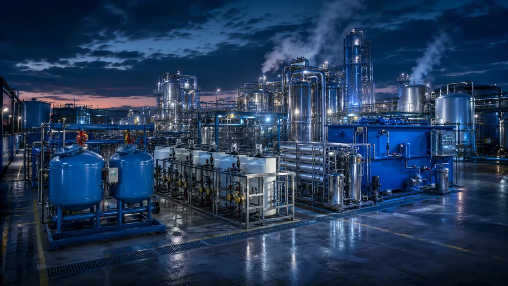
When a power plant or chemical facility faces a zero-liquid-discharge permit, the engineering strategy shifts from disposal to closed-loop recovery. The technical core of that transition is a ZLD wastewater treatment system — an integrated process that turns liquid effluent into reusable water and dry solids.
This guide explains the process architecture, technology trade-offs, and design factors that engineers and compliance teams must evaluate before committing to a full-scale ZLD installation.
The Engineering Logic: How a ZLD Wastewater Treatment System Works
A ZLD wastewater treatment system is an integrated sequence of separation stages—pretreatment, membrane concentration, and thermal evaporation—designed to recover 95–99% of wastewater as distillate for reuse, leaving only dry solids. Unlike conventional wastewater treatment processes that stop at discharge-quality effluent, ZLD pushes separation to the thermodynamic limit, closing the water loop entirely. For many industrial effluent treatment applications, this eliminates liquid discharge and its associated permitting risk. The engineering objective is to reduce brine volume step by step until only filterable cake remains, recycling every recoverable drop.
The Three Pillars of the ZLD Process Flow
Every ZLD configuration, regardless of vendor or site, rests on three process stages. The handover points between these stages are where most energy and reliability trade-offs are decided.
Stage 1: Pretreatment and Conditioning
Pretreatment protects downstream membrane and thermal equipment from scaling, fouling, and corrosion. Key objectives: suspended solids removal, hardness reduction, and pH adjustment. Common unit operations include lime softening, media filtration, and ultrafiltration. Without careful conditioning, a high‑recovery RO train can be knocked offline by silica scale within days. Engineers typically target turbidity below 1 NTU and LSI control to keep scale-forming ions in check.
Stage 2: Membrane Concentration
Membrane concentration uses high‑pressure reverse osmosis (HPRO) or electrodialysis reversal (EDR) to reduce brine volume before the thermal stage. Reverse Osmosis (RO) membranes can push total dissolved solids (TDS) from 10,000 mg/L up to 70,000–90,000 mg/L, depending on feed chemistry. Many ZLD trains now rely on advanced membrane filtration to shrink brine volume, cutting energy costs by up to 50% compared to a fully thermal design. The concentrate remains liquid, but with reduced flow, the thermal step becomes economically viable.
Stage 3: Thermal Evaporation and Crystallization
The final stage applies heat to drive off the remaining water, leaving crystalline solids. A brine concentrator (often an MVR evaporator) takes the membrane reject and brings TDS near saturation. The saturated slurry then enters a crystallizer, where controlled evaporation forces salt precipitation. This is the true zero-liquid step: the distillate is recovered, and the solid cake can be dewatered and sent to landfill or further refined for resource recovery. The shift from brine to wet cake is where energy intensity spikes, making this stage the central cost driver for the entire plant.
Comparing ZLD Technologies: Membrane vs. Thermal Systems
No single technology dominates all ZLD applications. The choice between membrane-based and thermal-based concentration depends on feed salinity, energy economics, and site utilities. Below is a comparative summary of the main technology blocks found in today’s large-scale ZLD installations.
| Technology Type | Energy Requirement (kWh/m³ treated) |
Typical TDS Range | Primary Use Case |
|---|---|---|---|
| Reverse Osmosis (HPRO) | 3–8 | Up to ~90,000 mg/L | Brine preconcentration ahead of a thermal step |
| Mechanical Vapor Recompression (MVR) | 10–30 | 50,000–250,000+ mg/L | Main evaporation stage; suitable when electricity is low‑cost |
| Multi‑effect Distillation (MED) | 5–15 (steam‑driven) | 50,000–300,000+ mg/L | Large installations with access to waste heat or low‑cost steam |
Energy figures are representative benchmarks. Actual consumption depends on feed chemistry, operating temperature, and equipment configuration. Request vendor projections for site‑specific performance.
For process engineers, the divide is clear: membrane‑based concentration saves energy when TDS is moderate, but only thermal systems can handle the near‑saturation brines that make ZLD possible. This energy‑balance question often drives the decision when an industrial water recycling comparison shows ZLD as the sole option where discharge is prohibited.
Key Components: Brine Concentrators and Crystallizers
The heavy machinery in a ZLD system — brine concentrator and crystallizer — are not interchangeable black boxes. The brine concentrator, typically an MVR evaporator, reduces brine volume to a point where the total solids loading makes boiling impractical without forced circulation. The crystallizer then receives this nearly saturated slurry and produces a solid that can be dewatered with a centrifuge or belt press.
- MVR evaporator: Recompresses vapor to supply latent heat, achieving a coefficient of performance (COP) of 10–20 at low temperature lifts; highly efficient when electricity is the main energy source.
- Forced‑circulation crystallizer: Designed to handle high‑viscosity, scaling‑prone brines; separates salts such as NaCl, Na₂SO₄, or mixed chlorides.
- Horizontal vs. vertical tube: Horizontal tube falling‑film designs dominate brine concentration for moderate scaling potential; vertical tube forced‑circulation units are preferred when heavy scaling or high slurry density is expected.
The interaction between brine concentrator and crystallizer must be modeled with real site water, not just standard design curves. Pilot testing reduces the risk that the crystallizer will see an unexpected ionic mix leading to hydrate formation or rapid scaling.
Industrial Applications and Recovery Targets
ZLD installations are not generic; the contaminant profile of the raw wastewater drives membrane selection, metallurgy, and the type of crystallizer required. The table below summarizes recovery targets and common problem species for four high‑water‑stress sectors.
| Industry | Common Contaminants | Typical Water Recovery Target |
|---|---|---|
| Power generation | Silica, calcium, magnesium, sulfates | 95–98% (cooling tower blowdown) |
| Oil & gas | Chlorides, barium, strontium, organics | 90–97% (produced water / flowback) |
| Textile processing | Dyes, high COD, sodium chloride | 90–95% (dye‑bath effluent) |
| Mining | Heavy metals, sulfates, arsenic | 95–99% (tailings pond water) |
Recovery ranges shown are achievable with properly sequenced DAF, UF, RO, and thermal stages. Exact values depend on feed chemistry and pretreatment. Pilot‑test with representative water before fixing plant guarantees.
- In power plants, ZLD often targets cooling tower blowdown where silica limits conventional RO recovery. A combination of HPRO and MVR can push overall site water recovery above 98%.
- For shale‑gas operations, ZLD handles fracking flowback water with TDS exceeding 100,000 mg/L, converting a disposal liability into reusable water for drilling or completion.
Many purchasers evaluate equipment for ZLD systems alongside process water systems to see if the recovery stream can directly feed into upstream utility water networks, improving the overall plant water balance.
Critical Design Factors for System Selection
ZLD is never a single‑specification purchase. The items below form a practical checklist for engineering teams before the RFQ stage.
- Influent water chemistry: Full ionic scan including TDS, hardness, silica, alkalinity, and volatile organics. Scaling ions like calcium sulfate or silica dictate the safe recovery limit of the RO step.
- Available plot space: Thermal evaporators have a significant footprint; vertical tube designs reduce it, but height restrictions may apply.
- Energy availability: Does the site have low‑cost steam (favoring a multi‑effect train) or primarily electric power (favoring MVR)? This decides the opex structure for the life of the plant.
- Solid waste disposal pathway: The cake from the crystallizer still requires landfill, incineration, or further processing. Characterize the solid early; some mixed salts are classified as hazardous.
- Pilot testing commitment: A 3‑6 month pilot run with at least a 5 m³/day unit is standard before finalizing a full‑scale design.
Vendors that push a standard package without reviewing your specific TDS and scaling ion profile are skipping the step that prevents most early failures. When you review industrial water treatment equipment, ask for reference plants that treat water chemistry within 20% of your own, not just a similar industry.
Consult with a ZLD Systems Engineer
ZLD projects are capital‑intensive and site‑specific; a feasibility study and FEED (Front‑End Engineering Design) package are standard before procurement. Our process engineers can review your waste stream profile, site energy costs, and discharge constraints to recommend a pretreatment‑membrane‑thermal sequence that avoids overdesign. For performance specifications on a water purification for ZLD front end, our team can align technology choices with your utility ecosystem. Request a technical consultation to define the water chemistry parameters that will drive all downstream decisions.
Frequently Asked Questions
What is the typical energy consumption of a ZLD system?
Energy use depends on the technology split. A combined RO‑MVR plant often consumes 15–25 kWh/m³ of treated wastewater, while a purely thermal multi‑effect plant can require 30–50 kWh/m³ equivalent. Mechanical Vapor Recompression (MVR) designs typically reduce electrical consumption by 50–70% compared to single‑effect distillation, making them the preferred evaporator when steam is not free.
Can ZLD systems recover saleable resources?
Yes — resource recovery is increasingly integrated into ZLD designs. Crystallizer stages can be tuned to produce high‑purity sodium chloride crystals or to isolate lithium, phosphate, or calcium sulfate. In mining and chemical plants, the sale of by‑product salts can partially offset operating costs, but economics depend heavily on local market prices and salt purity requirements.
How does ZLD impact operational compliance?
By eliminating all liquid discharge, a ZLD installation removes the risk of violating NPDES or equivalent permits. This is a major advantage for plants facing tightening Total Dissolved Solids (TDS) limits or seasonal flow restrictions. Compliance shifts from treating to an effluent standard to managing solid waste, which, while still regulated, is easier to control and monitor in a closed loop. Many teams revisit their wastewater treatment plant design criteria to ensure the new solid waste stream aligns with site permits.