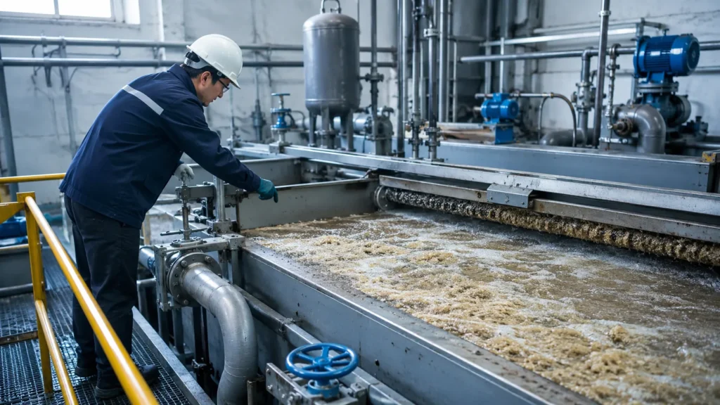
Cloudy effluent over the weir, a sludge blanket that refuses to lift, or a tank of clear water with no milky bubble curtain—these are the moments when DAF troubleshooting moves from routine checks to urgent action. This guide from WCT focuses on what you see at the tank’s edge and gives you the immediate steps to restore separation.
Before diving in: the diagnostics below apply to stationary dissolved air flotation equipment for wastewater and process water. If you’re looking for DAF truck vehicle troubleshooting, consult your engine diagnostic tools—this article is about flotation, not fuel injection.
Quick Diagnostic: DAF Symptom and Remedy Matrix
Use the table below to match what you see in the tank to a probable cause and immediate action. Most DAF failures show visible signs before effluent quality craters.
| Symptom | Likely Cause | Immediate Action |
|---|---|---|
| Cloudy effluent / fine solids carryover | Poor floc formation or insufficient bubble attachment | Check coagulant/polymer dosage; run jar test. Inspect white-water quality. |
| Large bubbles breaking the surface; clear water with no milky cloud | Low air saturation, clogged release nozzles, or PRV stuck open | Verify saturation tank pressure (normal range 60–80 psi). Clean nozzles; inspect pressure reducing valve. |
| Sludge blanket sinking or thin with no lift | Excessive floc density (polymer overdose), low A/S ratio, or skim cycle too fast | Reduce polymer feed; check recycle pump output; slow skimmer speed. |
| No white water; feed water appears unchanged | Recycle pump not running or air intake blocked | Confirm pump rotation, check suction line for blockage, inspect air flow meter. |
| Floc floating but solids dropping out quickly | Weak floc (pin floc) due to low dosage or high shear | Increase coagulant slowly; examine flash mix energy; ensure gentle flocculation zone. |
| Skimmer skips or does not remove float consistently | Worn skimmer blades, misaligned chain, or build-up on track | Inspect blade edge and tension; clean tracks; realign drive mechanism. |
Values and remedies are general guidelines. Always verify the specific operating ranges and maintenance procedures in your equipment manual.
Troubleshooting Microbubble Formation and Air Saturation
If the tank is not filled with a dense, milky curtain of microbubbles, separation will fail—no amount of chemical tweaking can compensate for poor air saturation. The heart of the DAF is the recycle loop; start your inspection there.
The Microbubble Test: Visual Indicators of Saturation Efficiency
A healthy DAF unit produces water that looks like skim milk, not clear water with scattered large bubbles. The microbubble size should be in the 30–100 micron range. When you see “clear” water with only churning froth on top, the air isn’t dissolving correctly.
What to check:
- Saturation tank gauge: Target pressure for most industrial units is 60–80 psi. A reading below 50 psi usually signals a leak, pump issue, or valve misadjustment.
- Pressure reducing valve (PRV): Listen for hissing or feel for vibration. A failing PRV can bleed off pressure before the nozzles.
- Nozzles and injection point: Remove and inspect a sample nozzle for scale, rust, or polymer fouling. Even partial blockage reduces the number of active bubbles.
- Visual check at the release zone: The flow into the tank should look uniformly white, not striated or “sparkling.” Large bubbles indicate undissolved air escaping.
Checking the Recycle Pump and Air Supply
The recycle pump must pull enough water and air into the saturation tank. Start with the basics:
- Cavitation noise: A rattling or gravel-like sound means the pump is starved. Check the suction strainer and ensure the flow to the pump isn’t restricted by a partially closed valve.
- Air flow meter: If the indicator stays at zero or jumps erratically, examine the air intake filter—fine dust can plug it within weeks.
- Pump motor amp draw: A drop in amps below normal running spec can indicate a worn impeller or air binding.
- Seal and gasket leaks: Even a small air leak on the suction side will break the vacuum needed to pull in air. Inspect all connections with soapy water.
Once the saturation loop is stable, the white-water column in the flotation zone should appear consistent across the width of the tank. If only half the tank shows milky flow, suspect one-sided nozzle blockages or uneven distribution plate wear.
Benchmarking System Performance: Operational Parameters
If the quick visual checks don’t reveal a clear culprit, compare your unit’s readings to the benchmarks our engineers use for industrial DAF systems. These ranges are a starting point for spotting slow-developing wear or a design mismatch.
| Parameter | Typical Range | What to Watch For |
|---|---|---|
| Recycle rate (% of influent flow) | 20–50% | Too low: insufficient air. Too high: hydraulic turbulence disturbs the sludge blanket. |
| Saturation pressure | 60–80 psi (4.1–5.5 bar) | Below 50 psi: poor air dissolution. Above 90 psi: excessive energy with marginal bubble improvement. |
| Air-to-solids (A/S) ratio | 0.02–0.06 | Below 0.02: weak float. Above 0.06: wasted air and possible floc disruption. |
| Retention time (minutes) | 20–45 minutes | Shorter: solids carryover. Longer: adequate separation but may indicate undersized unit for current load. |
| Surface loading rate (gpm/ft²) | 2–6 gpm/ft² (80–245 L/min/m²) | Exceeding high end: fine solids wash over the effluent weir. |
Ranges are provided as an example comparison target. Actual design specifications for your unit may differ. Request the factory datasheet or batch test reports from the manufacturer to establish the correct baseline for your system.
Chemical Dosing and Flocculation Failures
Even with perfect microbubbles, untreated or improperly conditioned solids won’t attach and rise. The interaction between coagulant dosage, polymer mixing, and floc structure must be tuned to the specific wastewater.
Signs of Coagulant or Polymer Imbalance
Walk up to the DAF tank and watch the float. If you see large, billowy “popcorn floc” that floats easily but leaves a murky water phase underneath, you are likely overdosing polymer—the floc traps water and sinks partially. Conversely, tiny “pin floc” that looks like suspended dust and refuses to coalesce indicates underdosing or insufficient mixing energy.
Other clues:
- Sheen or oil on effluent: Often a sign of free emulsified oil that coagulant failed to break. Check the flocculation chemistry with a jar test.
- Floc rising but then dispersing: Polymer chain breaking from excessive shear in the inline mixer or at the pump. Reduce mixing intensity.
- Dense, heavy floc that sinks after a few minutes: Too much metal coagulant (e.g., alum or ferric) causing high-density solids.
Testing Floc Strength and Adhesion
A simple jar test gives you a window into what’s happening in the full-scale unit. Fill a beaker with the conditioned dosed water, stir slowly for one minute, then let it settle. In a proper setup, floc should rise gently and stick together, not disintegrate at the slightest swirl.
Also test adhesion visually: take a sample from the flocculator effluent, add a small amount of air-saturated recycle water (if you can extract it safely), and watch if bubbles bind to the solids. If bubbles slide off the particles, the charge demand is not satisfied—adjust the coagulant first, then re-test polymer.
For precise dosing, using a reliable chemical dosing system with a metering pump prevents drift. Some plants also integrate a dedicated PAC/PAM dosing system when coagulant and polymer require separate conditioning zones.
Mechanical and Component Maintenance
Mechanical wear often causes subtle performance drops that operators blame on chemistry. Before adjusting the chemical feed, run through this checklist.
- Skimmer blade alignment and tension: Blades must contact the water surface evenly across the tank width. Gaps let floated solids spin past. Replace worn rubber or hinge pins.
- Sludge hopper blockages: Heavy or sticky sludge can bridge across the hopper mouth. Probe with a clean-out rod daily if the waste is fibrous or oily.
- Saturation tank internals: Every quarter, drain the tank and inspect the packing media or diffuser plates. Scale build-up reduces air-water contact area. Acid clean or replace as needed.
- Effluent weir levelness: An unlevel weir distorts flow patterns and short-circuits the tank. Use a hose level or laser to verify across all plates.
- Air release valve on saturation tank: This should not continuously bleed; if it does, the water level control inside the tank is stuck or the float switch is failed.
Preventative Maintenance Schedule for Industrial DAF Units
A short, consistent maintenance rhythm prevents most emergency calls. Adapt these intervals to your specific waste load and operating hours.
- Daily: Visual check of white-water appearance, effluent clarity, and skimmer operation. Listen for unusual pump noise.
- Weekly: Calibrate chemical dosing pumps using a graduated cylinder to confirm flow rate. Inspect skimmer tracks and clean debris from the sludge trough.
- Monthly: Check saturation tank pressure gauge accuracy against a calibrated gauge. Clean air intake filter. Grease skimmer chain and check tension.
- Quarterly: Drain the saturation tank, open manway, inspect internals. Lubricate recycle pump motor bearings if applicable. Full cleaning of the DAF tank floor to remove settled solids.
- Annually: Pull and test the recycle pump impeller. Rebuild or replace PRV internals. Comprehensive nozzle replacement if erosion is visible.
This schedule keeps the effluent quality stable and reduces the chance that a slow-developing problem goes unnoticed until a compliance violation occurs.
Technical Support and System Optimization
When you have followed through the diagnostics and the DAF still won’t hold performance, it’s time to bring in specialized support. Recurring pump seal failures, persistent chemical overdosing, or an A/S ratio that cannot be held steady often point to a design mismatch or a deeper mechanical fault that requires factory-level evaluation. In those cases, scheduling a technical audit can uncover the root cause faster than trial-and-error field adjustments.
If your DAF unit is aging and component availability is becoming a problem, or if you are considering a more efficient DAF system, our team can help you evaluate modern options that match your current flow and contamination profile. We also offer guidance on integrating dosing system options and post-DAF polishing steps like a sand media filter where permit limits demand further TSS reduction.
Frequently Asked Questions
Why is my DAF sludge sinking instead of floating?
Sludge that sinks typically has too low an air-to-solids ratio or contains overly dense floc from excessive metal coagulant. Reduce the coagulant feed slightly and confirm that the recycle pump is delivering the design air volume. If the sludge appears heavy and granular, the polymer dose may also be too high, pulling solids into a tight floc that air cannot lift.
How much air should a DAF system use?
Most industrial DAF units operate with an air-to-solids ratio between 0.02 and 0.06. In terms of flow, the recycle stream often carries about 8–12% air by volume at standard conditions, translating to roughly 0.02–0.05 scfm per gpm of recycle flow. Verify your system’s design spec; over-aeration wastes energy and can actually break up floc.
Does this guide cover DAF truck diagnostics?
No. This article addresses dissolved air flotation systems used in wastewater and process water treatment. For DAF truck engine or vehicle system diagnostics, consult the vehicle manufacturer’s maintenance software or an authorized service center. The troubleshooting steps here apply only to stationary industrial water treatment equipment.