When a facility expansion collides with tight floor space and a hard construction deadline, conventional field-erected treatment plants can become a scheduling and cost liability.
A water treatment skid manufacturer changes the equation by delivering a skid-mounted water treatment system that is pre-engineered, factory-tested, and ready for rapid integration.
The rise of modular skid design has moved the primary quality and schedule risk from a remote job site into a controlled fabrication shop, where repeatability and inspection replace unpredictable field labor.
System Architecture: The Engineering Behind Skid-Mounted Treatment
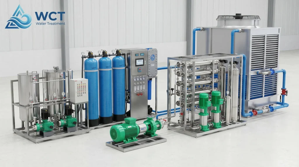
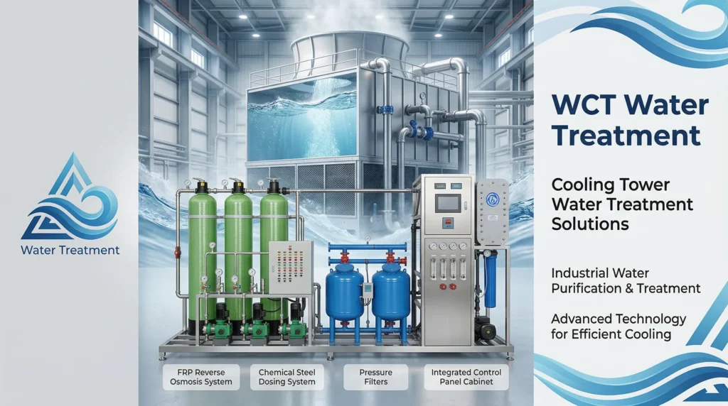
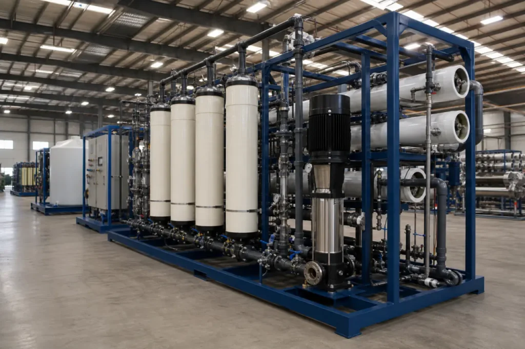
A skid-mounted water treatment system is a fully integrated, pre-piped, and pre-wired process unit built on a common structural frame. Every major component-pumps, vessels, instrumentation, valves, and controls-is mounted, aligned, and tested as a single assembly before it leaves the factory.
Structural Frame and Floor Space Efficiency
The skid frame is typically fabricated from epoxy-coated carbon steel or stainless steel, with forklift pockets and lifting lugs designed into the structure.
Because all components share a common base, the system occupies a defined, predictable footprint. This makes system footprint optimization much easier than with stick-built plants, especially in brownfield expansions and congested mechanical rooms.
Unlike larger packaged water treatment plants that often use containerized enclosures, a bare-skid approach lets you place the equipment inside an existing building, under a canopy, or on an elevated platform-reducing the cost of weatherproofing and auxiliary structures.
Centralized Process Control and Single-Point Connections
Integrated PLC panels centralize all motor controls, instrumentation signals, and alarm logic. The skid typically ships with a single-point main electrical connection and common inlet/outlet headers, eliminating the need to run conduit and tubing between separate piecemeal components on site.
This architecture shifts the most labor-intensive and error-prone work-welding, wiring, instrument calibration, and control logic validation-from a variable field environment into a shop floor subject to rigorous quality assurance.
Technical Specifications by Skid Type
Custom skids are configured for primary filtration, membrane separation, or targeted chemical dosing depending on feed water quality and the required output spec. The table below summarizes four common configurations and their typical engineering parameters.
| Skid Type | Primary Function | Typical Footprint / Capacity Range | Key Mechanical Components |
|---|---|---|---|
| Reverse Osmosis (RO) Skid | Dissolved solids, salinity, and micro-contaminant removal | 2-500 GPM; compact single-pass frames to multi-stage arrays | High-pressure pump, ASME membrane housings, CIP connections, permeate and concentrate flowmeters |
| Chemical Dosing Skid | Precise injection of coagulants, pH adjusters, or antiscalants | Compact wall-mount to full floor frames; injection rates from 0.1 to 50+ GPH | Metering pumps, calibration columns, pulsation dampeners, corrosion-resistant wetted parts |
| Media Filtration Skid | Suspended solids, turbidity, iron, and organics reduction | 10-500+ GPM; multi-vessel backwash-ready configurations | Automatic backwash valves, media tanks, differential pressure switches, service/bypass manifolds |
| Ultrafiltration (UF) Skid | Fine particulate, bacteria, and virus barrier | 5-300 GPM; hollow-fiber membrane modules on shared rack | Feed and CIP pumps, strainers, integrity test panel, turbidity and particle monitors |
Reverse osmosis skids (reverse osmosis systems) and ultrafiltration units are often paired for high-purity applications. Chemical injection skids (integrated dosing systems) are routinely built as standalone modules or integrated into the same frame for a complete pre-treatment train.
When to Combine Multiple Skids
A single-skid approach works well for simple filtration or pH correction, but many industrial processes require a sequence: chemical dosing for coagulation, multimedia filtration, and then RO/UF polishing.
In these cases, custom skid fabrication links multiple modules through pre-engineered interconnecting piping, keeping the system fully documented and factory-validated.
Industrial Application Fit Matrix
Selecting the right skid architecture starts with your specific contaminant profile, flow regime, and discharge or reuse targets. The matrix below maps common industrial sectors to typical treatment assignments.
| Industrial Sector | Typical Feed Water Challenge | Recommended Skid Configuration | Material Standard |
|---|---|---|---|
| Food & Beverage | Biological fouling, organics, hardness | RO + UV disinfection + chemical dosing skid for sanitization and antiscalant | Sanitary 316L SS, food-grade gaskets |
| Mining / Heavy Industry | Suspended solids, heavy metals, scaling ions | Chemical dosing (coagulation / flocculation) + media filtration + RO polishing | Epoxy-coated steel frame, lined pipe for abrasive streams |
| Chemical Processing | pH extremes, solvents, targeted contaminant load | Chemical dosing (pH neutralization) + carbon filtration or selective ion exchange | PVC / CPVC or 316L SS depending on chemical compatibility |
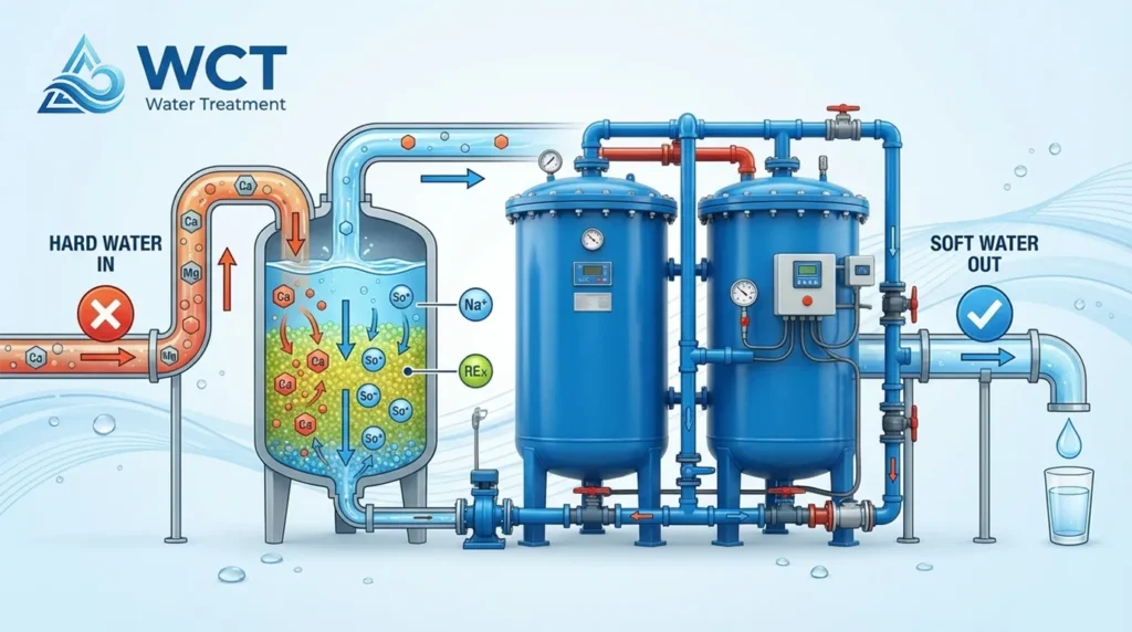
| Municipal / Commercial | Hardness, iron, manganese, general turbidity | Media filtration + softener or low-pressure RO on a compact integrated skid | Epoxy-coated carbon steel; stainless for potable water contact |
Wastewater Reuse and ZLD Preparation
Many facilities now treat process water for reuse rather than discharge.
A modular water treatment skid designed for reverse osmosis concentrate recovery or softening ahead of an evaporator can serve as the front end of a zero liquid discharge (ZLD) strategy.
The same skid-based approach keeps future expansion straightforward: additional modules simply plug into the header and the control system.
The Custom Engineering and Selection Process
Proper skid design begins with a thorough feed water analysis and a clear definition of site constraints. The following steps turn those inputs into a factory-ready fabrication package.
- P&ID development and 3D CAD modeling: The process flow is converted into a piping and instrumentation diagram, then into a three-dimensional model. This lets you verify maintenance clearances, valve access, and instrument visibility before any metal is cut.
- Component sizing based on peak flow rates: Pumps, membrane housings, dosing tanks, and pipe diameters are selected for the maximum sustained flow, not just the average. Oversizing to a large buffer adds cost; undersizing creates a chronic bottleneck.
- Material selection for chemical compatibility and pressure: Wetted parts must handle the full chemical range-acids, caustics, oxidizers-and the highest expected operating pressure. A pH swing from 2 to 12 in the same process line demands a detailed compatibility review.
- Controls and automation integration: The skid PLC is programmed to communicate with your plant’s top-end SCADA or DCS. Typical monitoring points include inlet/outlet quality, pump status, tank levels, and critical alarm contacts, all proven during factory testing.
Throughout this process, custom skid fabrication ensures that every bracket, port, and instrument position matches the as-built model, removing the guesswork that plagues field-routed installations.
Manufacturer Evaluation and Factory Acceptance Testing (FAT)
A reliable manufacturer will not ship a skid until it passes a thorough Factory Acceptance Testing protocol. FAT validates mechanical integrity, electrical safety, and control logic under conditions that closely mirror the intended operation.
Use the checklist below to evaluate a potential skid partner’s quality program.
- Shop fabrication certifications: Verify ASME pressure vessel code stamps, AWS-certified welders, and documentation of weld procedure specifications. If the skid will handle potable water or food-contact streams, confirm the shop follows sanitary fabrication standards.
- Hydrostatic pressure testing: All piping and vessels should be pressurized to at least 1.5 times the design operating pressure and held for a documented period, with no visible leaks or pressure drop outside the allowed tolerance.
- Dry and wet electrical testing: Motor rotation, continuity, insulation resistance, and emergency stop functions are tested before fluid ever enters the system. A wet test then confirms pump performance, level switches, and flowmeter accuracy under load.
- PLC logic and I/O verification: Every digital and analog input/output point is forced or simulated to verify that the control panel reads sensors, drives actuators, and triggers alarms correctly. The full sequence-startup, normal run, shutdown, and fail-safe-should be cycled at least twice.
- Component and spare parts documentation: Request a final certified as-built P&ID, a complete bill of materials, and a recommended critical spares list. A manufacturer that treats these documents as afterthoughts often cuts corners on fabrication consistency as well.
When FAT is completed before the skid leaves the factory, on-site commissioning typically shrinks from weeks of troubleshooting to days of final tie-in and performance verification. That is the core value a disciplined turnkey water treatment fabricator brings.
Preparing Your Site Data for a Custom Skid Quote
An accurate engineering proposal requires more than a verbal description of the problem. Have the following information ready before you submit a request for design and pricing.
- Complete water analysis: A lab report covering TDS, hardness, iron, manganese, silica, pH, turbidity, and organic load. For wastewater reuse, include the effluent permit limits or reuse quality targets.
- Peak and average flow rates: Specify both in gallons per minute (GPM) or cubic meters per day (m³/day). A system sized only for average flow will struggle during peak production periods.
- Available footprint and access constraints: Provide a dimensioned sketch or marked-up site plan showing the skid location, doorways, overhead clearance, and any obstructions. Include utility connection points for power, drain, and service water.
- Target treated-water quality: State the required specification for the water coming off the skid-conductivity for RO permeate, turbidity for filtration, or microbial limits for sanitary processes.
When you have your water analysis, flow targets, and site dimensions documented, submit your project inputs to WCT’s engineering team.
We will review the data against proven treatment configurations and begin the custom skid design discussion-starting with your specific operating conditions, not a generic catalog unit.