A precise sedimentation tank design relies on translating fluid dynamics into controllable gravity solids-liquid separation. Sizing a primary or secondary clarifier requires balancing suspended solids settling velocity, hydraulic surface loading, and sludge accumulation limits to eliminate particulate carryover.
Primary Design Parameters and Operational Criteria
Sedimentation tank performance depends primarily on hydraulic surface loading rate rather than gross liquid depth. When sizing a clarifier, engineers evaluate peak hourly flows against particle terminal settling velocities.
For gravity settling to occur, the upward fluid velocity must remain lower than the discrete or flocculent settling speed of target particles. Excessive surface loading forces light suspended solids over effluent weirs.
Core Sizing Variables: Overflow Rate vs. Retention Time
Surface loading rate defines the volume of wastewater applied per unit of tank surface area per day. Typical values range from 15 to 30 m3/(m2 day) for primary clarifiers.
Hydraulic retention time governs the contact time provided for particles to settle into the floor hopper. While discrete settling relies purely on settling velocity, flocculent settling uses hydraulic surface loading rate calculations alongside empirically derived isoremoval plots.
| Parameter | Primary Clarifier Standard | Secondary Clarifier Standard | Design Significance |
|---|---|---|---|
| Hydraulic Surface Loading Rate (m3/m2 day) | 24 – 32 | 16 – 24 | Dictates required surface area footprint |
| Hydraulic Retention Time (hours) | 1.5 – 2.5 | 2.0 – 4.0 | Ensures adequate time for particles to reach floor |
| Weir Loading Rate (m3/m day) | 120 – 180 | 90 – 150 | Prevents localized high velocity near effluent troughs |
| Sidewater Depth (meters) | 3.0 – 4.5 | 3.5 – 5.0 | Provides clear settling zone above sludge blanket |
High solids loading in secondary clarifiers requires deeper sidewaters to isolate the sludge blanket from the settling zone. Lower overflow rates prevent light biological flocs from washing out during peak diurnal surges.
Rectangular vs. Circular Sedimentation Tanks
Selecting tank geometry changes mechanical sludge removal, footprint efficiency, and flow distribution patterns. Plants comparing a continuous DAF vs sedimentation tank setup must first settle on the right clarifier geometry.
Rectangular Settling Basins (Plug Flow)
A rectangular settling basin operates under plug-flow dynamics, directing water uniformly from the inlet wall toward the discharge weir. This configuration allows common-wall construction, reducing site land consumption and civil work expenses.
To prevent short-circuiting, rectangular tanks maintain a minimum length-to-width ratio of 4:1. Maintaining a 4:1 to 6:1 aspect ratio ensures cross-sectional flow distribution remains stable across varying intake velocities.
Adding high-density plate modules or inclined tube packing systems can multiply effective settling area within rectangular footprints, cutting required tank volume by up to 50 percent.
Circular Clarifiers (Radial Flow)
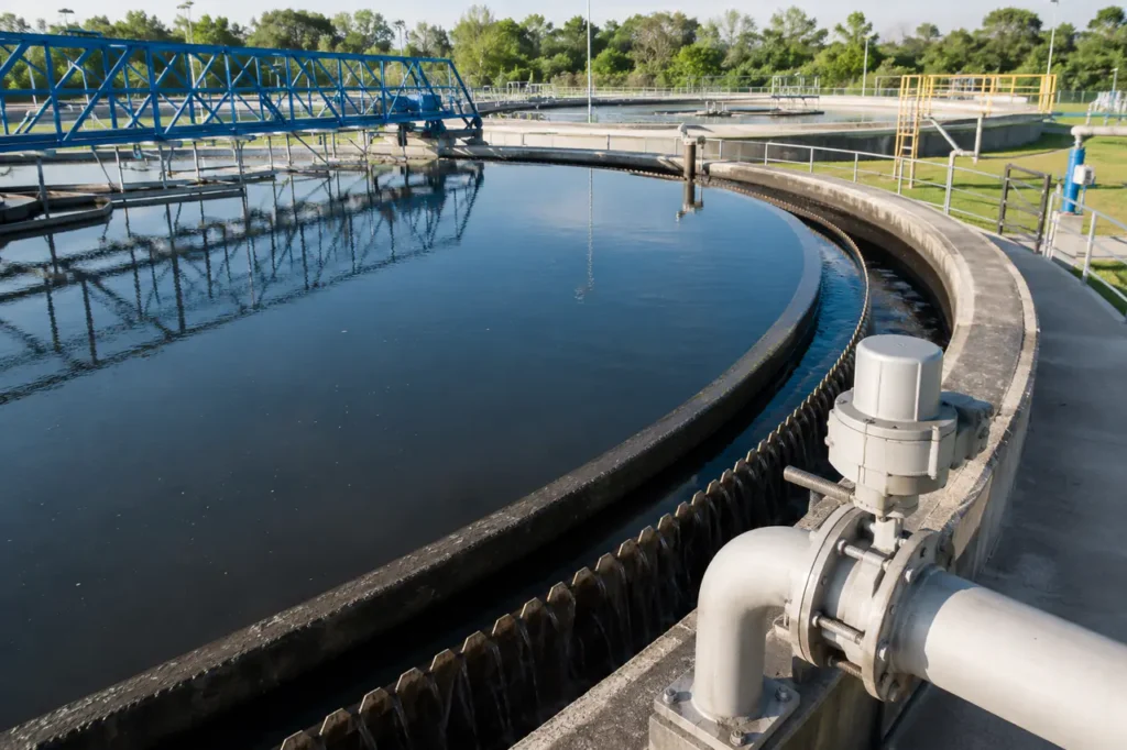
Circular clarifiers utilize radial flow, feeding raw wastewater through a central distribution well and expanding outward toward a perimeter weir trough. Velocity naturally drops as radius increases, aiding particle settling.
Mechanical sludge scrapers rotate around a central drive shaft, pushing settled solids into a central sump. This continuous removal minimizes sludge retention time and prevents septic gas formation in municipal plants.
| Design Factor | Rectangular Settling Basin | Circular Clarifier |
|---|---|---|
| Hydraulic Flow Pattern | Plug flow with linear travel path | Radial flow expanding from center well |
| Footprint Efficiency | High efficiency via common-wall builds | Requires isolated footprints and spacing |
| Sludge Collector Mechanics | Chain-and-flight or traveling bridge scrapers | Central rotating scraper arms with bottom blades |
| Inlet Disturbance Resistance | Sensitive to inlet baffle configuration | Highly stable radial deceleration zone |
Evaluating geometric trade-offs before freezing civil layouts prevents costly structural redesigns late in plant engineering:
- Choose rectangular basins when site land is tightly constrained or multi-tank parallel expansion is planned.
- Choose circular clarifiers when continuous, low-maintenance mechanical sludge scraping is a primary operational goal.
- Choose tube settler retrofits in rectangular layouts when upgrading treatment plant hydraulic capacity within existing civil basins.
Step-by-Step Engineering Calculation Process
Clarifier calculation flows from peak hydraulic flow rates through surface area sizing, depth selection, aspect ratio geometry, and scouring velocity validation.
Standard municipal and industrial wastewater treatment plant design follows a linear mathematical sequence to guarantee effluent solids concentration limits.
1. Calculating Required Surface Area
The primary surface area calculation uses peak hourly flow and design overflow rate limits. Surface area dictates whether suspended solids settling velocity exceeds liquid upward velocity.
- Formula: Surface Area (A) = Q_peak / Overflow Rate
- Q_peak: Maximum design peak flow rate (m3/day or m3/h)
- Overflow Rate: Target hydraulic surface loading rate (m3/m2 day)
If the design peak flow is 12,000 m3/day and maximum allowable overflow rate is 30 m3/m2 day, the total surface area must equal at least 400 square meters across operational tanks.
2. Determining Tank Volume and Depth
Total tank volume is calculated using target hydraulic retention time under average daily flow conditions to ensure complete physical clarification.
- Formula: Tank Volume (V) = Q_avg * HRT
- Q_avg: Average daily design flow (m3/h)
- HRT: Required hydraulic retention time (hours)
Sidewater depth equals volume divided by surface area. Designers then add mandatory allowances for sludge accumulation volume, clear liquid surface margin, and freeboard depth.
- Clear settling depth zone: 2.0 to 3.0 meters
- Sludge storage accumulation zone: 0.5 to 1.5 meters
- Structural freeboard margin: 0.3 to 0.6 meters above maximum water level
3. Sizing the Dimensions (Length, Width, or Diameter)
After establishing total area, engineers select clarifier dimensions using standard structural ratios and equipment mechanical limits.
- Rectangular basins: Set Width (W) based on scraper mechanism spans (3 to 10 meters). Calculate Length (L = A / W) and verify L:W ratio is at least 4:1.
- Circular clarifiers: Compute Diameter D = sqrt((4 * A) / 3.14159). Verify D falls within standard drive mechanism limits (6 to 45 meters).
- Multi-unit distribution: Divide calculated total surface area across at least two parallel units for maintenance redundancy.
4. Calculating Flow-Through Velocity and Weir Length
Horizontal flow-through velocity must remain below critical scouring velocity to prevent settled sludge from resuspending into the effluent stream.
- Horizontal Velocity: v_h = Q_peak / (Total Width * Depth)
- Velocity limit: Keep v_h below 0.005 m/s to prevent bed scouring
- Weir Loading Rate: WLR = Q_peak / Total Weir Length
- Weir length limit: If WLR exceeds 150 m3/m day, add internal perimeter or finger launders
Inlet and Outlet Zone Specifications
Hydraulics at tank boundaries dictate real-world efficiency. Poor inlet dissipation or high weir overflow velocities bypass effective settling volumes.
The inlet structure must evenly distribute incoming flow across the entire cross-section to maintain uniform settling velocities and prevent dead zones.
Inlet Baffle Design and Energy Dissipation
Raw influent enters with significant kinetic energy. An unbaffled inlet creates jetting currents that sweep straight across the tank bottom, causing extreme short-circuiting.
Properly designed target baffles and perforated walls convert concentrated pipeline momentum into a uniform planar velocity front across the cross-section.
- Submerged baffle depth: Extend 0.5 to 1.0 meter below liquid surface.
- Perforated wall porosity: Target 10 to 20 percent total open wall area with evenly spaced port diameters.
- Central well velocity (circular): Maintain energy dissipation well velocities below 0.4 m/s to preserve floc integrity.
Outlet Weir Troughs and Effluent Launder Design
Effluent exit zones use V-notch weirs (typically 90-degree V-notches spaced at 150 to 300 mm) to maintain uniform withdrawal rates along the entire perimeter or trough length.
Installing double-sided effluent launders increases available weir length, successfully suppressing local crest velocities during peak wet-weather surge flows.
Sludge Storage and Scraping Mechanism Design
Mechanical sludge handling systems must match solids loading rates to extract accumulated sludge before septic gas generation or scouring occurs.
In a typical primary sedimentation water treatment process, settled sludge accumulates rapidly near the inlet end, requiring dedicated deep collection hoppers.
Bottom Slope Geometry and Sludge Hopper Sizing
Clarifier floor geometry must encourage settled solids toward extraction sumps without creating stagnant pockets or requiring excessive manual flushing.
- Rectangular floor slope: 1 to 2 percent sloped downward toward the inlet end hopper.
- Rectangular hopper wall angles: Minimum 50 to 60 degrees from horizontal to ensure gravity sludge consolidation.
- Circular tank floor slope: 1:12 (approx. 8 percent) sloping continuously inward toward a center sludge pit.
Mechanical Scraping Mechanism Selection
Continuous mechanical scraping equipment keeps sludge moving toward discharge lines while preventing toxic or septic solids buildup.
- Flight-and-chain collectors: Non-metallic chains and plastic flights continuously drag bottom sludge to hoppers while scraping surface scum.
- Traveling bridge scrapers: Span rectangular basins and drag bottom squeegees periodically; best for wide multi-bay installations.
- Rotating collector arms: Structural trusses in circular tanks fitted with neoprene squeegee blades that sweep settled solids into center sumps.
Site Compliance and Construction Standards
Engineering specifications must incorporate local regulatory margins, peak wet-weather surge capacity, and structural verification testing.
Municipal environmental codes enforce baseline hydraulic standards to prevent untreated overflows during severe weather events. Following established industrial water system design protocols ensures long-term operational compliance.
Operational Redundancy and Maintenance Verification
Regulatory frameworks rarely permit single-unit sedimentation designs for continuous discharge facilities. Site engineering plans must incorporate structural and mechanical redundancy checks prior to final approval.
- Parallel train count: Provide a minimum dual parallel train configuration (two tanks at 50% total peak capacity each).
- Emergency bypass overflow: Size emergency spillways to divert excess storm surges safely to equalization basins.
- Hydrostatic leak testing: Require 24- to 48-hour concrete basin hydrostatic pressure holding tests prior to mechanical commissioning.
- Scour prevention checks: Verify horizontal velocities under 150% peak hydraulic loading to prevent effluent solids limit violations.