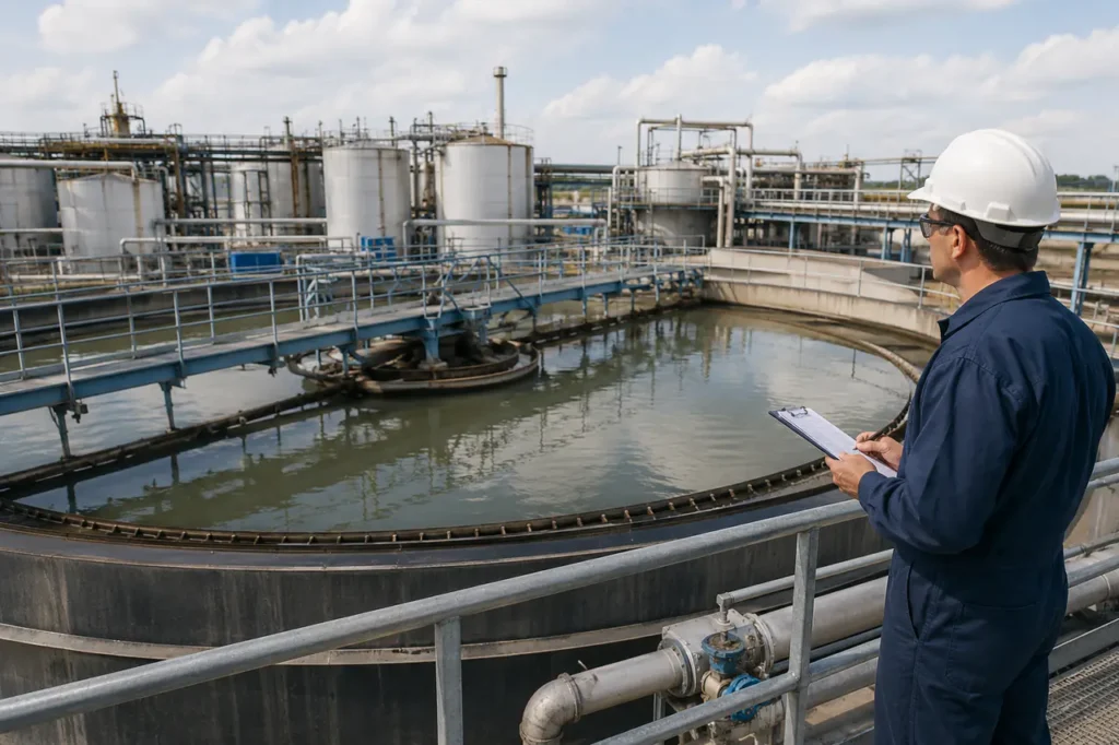
Unplanned solids carryover in industrial process streams leads directly to regulatory penalties, excessive chemical consumption, and rapid downstream equipment fouling. Specifying the correct industrial clarifier system requires evaluating raw feed hydraulics, particle settling rates, and available site footprint rather than installing a standard settling tank.
Integrating a fit-for-purpose clarifier for industrial wastewater stabilizes primary solid-liquid separation. This keeps downstream biological reactors, filtration media, or membrane units operating within target hydraulic and contaminant limits.
Core Principles of Industrial Clarification
Industrial clarification relies on gravity sedimentation, enhanced fluid dynamics, and chemical pre-treatment to separate suspended solids from liquid effluent. Raw wastewater entering a clarifier contains particles of varying sizes, densities, and electrical charges that dictate how quickly they drop out of suspension.
Unconditioned heavy particles settle naturally given sufficient time. However, colloidal solids remain suspended indefinitely due to electrostatic repulsion. Effective clarification requires converting turbulent inlet streams into a quiescent flow environment while encouraging fine particles to aggregate into larger, heavier flocs.
Settling Kinetics and Particle Behavior
Particle separation in gravity clarifiers follows Stokes’ Law, where settling velocity depends directly on particle diameter and density relative to the surrounding liquid. In untreated industrial wastewater, small colloidal particles settle at rates below 0.01 meters per hour, requiring unfeasibly large basins to clarify flow.
- Particle diameter and density difference drive terminal settling velocity.
- Liquid viscosity and temperature shift clarification residence time.
- Inlet energy must be dissipated to protect the quiescent zone.
- Colloidal repulsion keeps fine solids suspended unless coagulant charge neutralization is added.
Controlled flow velocities allow particles with settling speeds above the liquid rise rate to drop into the lower sludge zone, producing a clear liquid overflow.
Chemical Conditioning and Micro-Floc Formation
Chemical pre-treatment accelerates separation by neutralizing surface charges on colloidal suspended solids. Coagulants such as polyaluminum chloride (PAC) or ferric chloride compress the double layer around particles, allowing them to clump together upon contact.
- Coagulants neutralize surface charge and compress the particle double layer.
- Flocculation polymers bridge destabilized micro-flocs into denser macro-flocs.
- Automated dosing control matches coagulant feed to real-time turbidity and flow.
- Under-dosing risks solids carryover; over-dosing wastes chemical budget.
Integrating an automated PAC PAM dosing system ensures exact chemical delivery based on real-time flow and turbidity.
Evaluating Core Industrial Clarifier Technologies
Selecting the right clarifier design depends on the total suspended solids (TSS) load, particle density, footprint limits, and flow variability. Four primary clarification technologies dominate industrial process water treatment.
Circular Sedimentation Clarifiers
Circular clarifiers are the traditional workhorse for large-volume industrial applications. Effluent enters through a central feedwell that dissipates hydraulic energy, directing water slowly outward toward peripheral overflow launders.
Heavy solids settle to the sloped tank bottom, where continuous mechanical rake arms scrape sludge into a central discharge hopper.
These systems excel at handling high volumetric flows and fluctuating solids concentrations. Utilizing circular clarifier water treatment designs provides large sludge storage capacity, making them ideal for heavy industrial primary settling and municipal process streams.
Incline Plate (Lamella) Clarifiers
Incline plate or lamella clarifiers optimize space by stacking sloped plates at 55 to 60-degree angles inside a compact basin. Water flows upward between the plates while solids settle onto the plate surfaces and slide down into an underflow hopper.
This inclined arrangement increases the effective settling area up to ten times relative to the physical basin footprint. Lamella systems are ideal for indoor installations, space-constrained retrofit projects, and applications with consistent, chemically conditioned solids.
Dissolved Air Flotation (DAF) Systems
Dissolved Air Flotation reverses the gravity settling mechanism by floating suspended matter to the liquid surface. A recycled stream of clarified water is saturated with pressurized air and injected into the inlet zone, releasing micro-bubbles measuring 20 to 50 microns in diameter.
These micro-bubbles attach to light colloidal solids, fats, oils, and greases (FOG), carrying them to the surface to form a thick sludge blanket. Top-mounted skimmers continuously remove the floated sludge, delivering high effluent clarity for low-density or oily waste streams.
Ballasted Flocculation Systems
Ballasted flocculation adds micro-sand or dense ballast material along with polymer into the flocculation step. The heavy sand acts as a seed core, forming dense flocs that settle up to twenty times faster than conventional chemical flocs.
This high-rate process allows for extremely compact basin volumes and rapid start-up times. Ballasted systems excel at handling sudden peak flow spikes, high-turbidity surface water, and weather-driven storm surges in industrial treatment plants.
| Clarifier Technology | Target Contaminants | Footprint Requirement | Hydraulic Loading Rate | Chemical Dependency |
|---|---|---|---|---|
| Circular Clarifier | Heavy TSS, mineral solids, biological sludge | Large (100% baseline) | 1.0 – 2.5 m3/m2/h | Low to Moderate |
| Incline Plate (Lamella) | Fine inorganic TSS, metal hydroxides | Compact (15 – 20% of baseline) | 1.5 – 3.5 m3/m2/h | Moderate |
| Dissolved Air Flotation | Fats, oils, grease (FOG), light organic flocs | Small (30 – 40% of baseline) | 4.0 – 12.0 m3/m2/h | Moderate to High |
| Ballasted Flocculation | Variable TSS, high-turbidity shock loads | Minimal (10 – 15% of baseline) | 15.0 – 40.0 m3/m2/h | High (Ballast + Polymer) |
Energy cost trade-offs separate these technologies in field operation.
- Gravity clarifiers minimize power use but require the largest process area.
- DAF trades air saturation energy for compact removal of light FOG and colloids.
- Ballasted systems trade chemical and pumping cost for the smallest surge-rated footprint.
- Lamella units fit indoor retrofits where vertical space exists and feed solids are consistent.
Clarifier System Components and Mechanical Design
Mechanical durability determines the long-term reliability of an industrial clarifier. Corrosive process chemicals, high torque loads, and continuous abrasion require rugged structural components engineered for harsh operational environments.
- Energy-dissipating feedwells stabilize inlet turbulence.
- Rake arms and sludge scrapers control underflow collection.
- Effluent launders and V-notch weirs maintain even clarified water withdrawal.
- Scum baffles and skimmers isolate floating debris before discharge.
Energy Dissipating Feedwells
Influent piping delivers raw wastewater at relatively high velocities. Central feedwells convert this turbulent inlet momentum into smooth, low-velocity laminar flow, preventing short-circuiting across the settling basin and protecting the establishing sludge blanket.
Scraper Mechanisms and Rake Arms
- Spiral scrapers push settled solids toward the center sump in heavy-duty applications.
- Suction headers withdraw thinner sludge blankets where underflow density is lower.
- Sludge scraper clarifier mechanisms prevent solids from compacting into immovable deposits.
Effluent Launders and Weirs
- Perimeter or surface launders collect clarified water with minimal turbulence.
- Adjustable V-notch weirs keep local flow velocity below scour thresholds.
- Even withdrawal prevents settled solids from being pulled back into the clean discharge.
Scum Baffles and Skimming Systems
- Scum baffles trap floating grease, foam, and light debris before the weir.
- Rotating skimmer arms move surface scum into separate disposal boxes.
- Continuous skimming keeps surface contaminants out of downstream treatment.
Application Matrix: Matching Systems to Industry Profiles
Different manufacturing and washing operations produce vastly different wastewater profiles. Matching clarifier design to site feed chemistry prevents operational failures such as plate fouling, rake arm binding, or excessive chemical costs.
- Does the stream contain heavy abrasive mineral solids?
- Are metal hydroxides the dominant suspended phase?
- Is FOG or low-density organic material the main separation problem?
- Does hydraulic load swing widely across shifts or weather events?
Mining, Sand, and Aggregate Operations
Aggregate washing, mineral processing, and mining runoff generate high-volume streams loaded with dense, abrasive mineral solids at TSS levels often exceeding 10,000 mg/L. Heavy solids demand deep cone circular thickeners or high-torque lamella units fitted with hardened steel scraper blades to handle intense underflow weight.
Metal Finishing, Plating, and Automotive Manufacturing
Metal plating and surface finishing operations produce rinse waters containing dissolved heavy metals such as copper, nickel, chrome, and zinc. Chemical precipitation transforms dissolved ions into heavy metal hydroxides.
Incline plate clarifiers are the industry standard here, capturing fine chemical flocs within a compact indoor plant footprint.
Food, Beverage, and Meat Processing
Food processing plants discharge effluent high in organic matter, emulsified fats, animal proteins, and vegetable oils. Because these organic solids have specific gravities close to water, standard gravity settling is slow and inefficient.
DAF systems excel in these plants, recovering valuable fats and reducing biochemical oxygen demand (BOD) prior to discharge.
Municipal Wastewater and Industrial Parks
Centralized industrial effluent plants receive mixed waste streams with wide swings in flow rate, pH, and solids concentration. Large circular clarifiers offer the buffer volume needed to absorb hydraulic surges, maintaining continuous solid-liquid separation ahead of secondary biological reactors.
| Industry Sector | Wastewater Profile | Recommended System | Primary Operating Constraint |
|---|---|---|---|
| Mining & Aggregates | Very high TSS, heavy mineral grit, abrasive slurries | High-Torque Circular Thickener | Extreme rake torque load and abrasive component wear |
| Metal Finishing | Low TSS, metallic hydroxide precipitates, acid/alkali pH | Incline Plate (Lamella) Clarifier | Strict upstream pH adjustment and flocculation control |
| Food Processing | High FOG, emulsified fats, low-density organic solids | Dissolved Air Flotation (DAF) | Skimmer maintenance and saturation bubble nozzle scaling |
| Industrial Parks | Fluctuating TSS, variable organic loads, high hydraulic peaks | Ballasted Flocculation / Circular | Shock load buffering and variable chemical dosing control |
Engaging a specialized wastewater treatment system integrator ensures these primary solids removal systems interface smoothly with equalizing tanks, chemical dosing skids, and automated discharge monitoring systems.
System Sizing, Footprint, and Operational Constraints
Proper clarifier sizing relies on two primary engineering metrics: Surface Overflow Rate (SOR) and Hydraulic Retention Time (HRT). Design engineers calculate SOR by dividing the maximum design flow rate by the effective settling surface area, expressed as m3/m2/day or gpm/ft2.
To achieve reliable clarification, the target particle settling velocity must exceed the calculated SOR. If hydraulic surges increase the rise rate beyond particle drop velocity, solids wash over the effluent weirs into the clean water channel.
Hydraulic Retention Time and Peak Surge Capacity
Standard gravity sedimentation basins need longer retention than high-rate units.
- Gravity sedimentation typically requires 2.0 to 4.0 hours retention.
- DAF and ballasted systems operate at 15 to 30 minutes under accelerated kinetics.
- Design for peak hourly flow, not daily average flow.
- Use upstream flow equalization for batch dumps or storm water ingress.
Sludge Blanket Density and Dewatering Integration
The primary job of the lower clarifier zone is thickening settled solids into a manageable sludge underflow.
- Thicker sludge blankets improve underflow solids concentration.
- Higher underflow density reduces wet sludge volume sent to dewatering.
- Filter presses, belt presses, and centrifuges perform better with consistent feed solids.
- ZLD applications require maximum underflow density to lower thermal drying costs.
Integrating an optimized primary clarifier within an industrial effluent treatment solution or a broader ZLD wastewater treatment system stabilizes downstream dewatering.
What to Prepare Before Clarifier System Design
Specifying a custom clarifier requires accurate site data. Submitting incomplete flow or water quality figures often results in oversized capital expenditure or chronic under-sizing during peak production shifts. Following industrial water system design best practices shortens engineering review cycles and ensures accurate system selection.
- Hydraulic Parameters: Average daily flow rate, peak hourly flow rate, minimum flow rate, and future site expansion allowances.
- Raw Influent Quality: Total Suspended Solids (TSS) range, settleable solids volume, Fats, Oils, and Grease (FOG) concentrations, temperature range, and pH limits.
- Effluent Target Requirements: Required output TSS concentration, turbidity limits (NTU), heavy metal limits, or downstream membrane inlet tolerances.
- Site Physical Constraints: Available floor footprint, overhead height clearance, indoor vs. outdoor placement, soil loading capacities, and climate protection requirements.
- Chemical and Operational Preferences: Preferred coagulants/polymers, available power utility limits, automation integration level, and sludge disposal target moisture.
Preparing this baseline dataset before consulting equipment manufacturers ensures your site receives precise equipment sizing, accurate budgetary pricing, and optimal chemical process recommendations tailored to your operational goals.
Frequently Asked Questions
What is the difference between a clarifier and a thickener?
A clarifier focuses primarily on producing a clear liquid overflow, removing light or low-density suspended solids from liquid streams.
A thickener prioritizes compressing settled underflow solids, using heavier torque drives, deeper rake blades, and pickets to extract water and produce a high-density sludge bed for dewatering.
Are clarifiers and sedimentation tanks the same thing?
Sedimentation is the physical process of solids settling out of liquid under gravity. A clarifier is the complete engineered unit-including chemical conditioning chambers, feedwells, rotating scraper arms, scum skimmers, and effluent weir channels-designed to continuously control and accelerate the sedimentation process at industrial scale.
Can an industrial clarifier remove dissolved solids (TDS)?
No. Industrial clarifiers remove total suspended solids (TSS), colloidal matter, and insoluble flocs. Dissolved minerals, salts, and soluble organic compounds pass through the clarifier intact and require downstream separation technologies such as reverse osmosis membranes, ion exchange resins, or evaporative crystallizers.