Most process engineers evaluate a liquid liquid hydrocyclone based on its pressure capacity and liner diameter. But the real bottleneck is rarely the hardware—it’s the droplet size distribution entering the inlet. If upstream pumps and valves have already sheared the dispersed phase into a stable emulsion of sub-20-micron droplets, even the best hydrocyclone geometry will struggle to meet discharge compliance.
We see this pattern often in produced water and chemical separation projects. The physics of centrifugal separation are unforgiving: efficiency collapses when droplet diameters fall below a critical threshold, regardless of how much pressure you apply. That’s why successful deployment hinges on system-level engineering, not just component selection.
Working Principles of the Liquid-Liquid Hydrocyclone
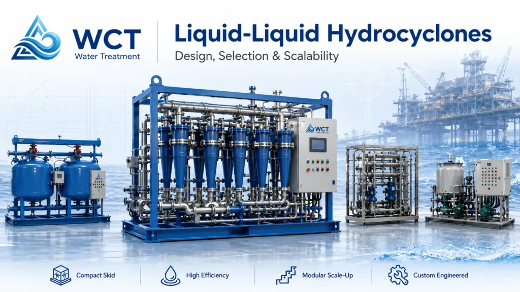
A liquid-liquid hydrocyclone is a static separation device that uses pressurized feed and a tangential inlet to generate high centrifugal force. It separates immiscible liquids purely by density difference, with no moving parts, relying on vortex formation to split the light and heavy phases.
Tangential Velocity and Vortex Generation
The tangential inlet converts feed pressure into rotational kinetic energy. As the fluid enters, it creates a high-velocity outer spiral—a primary downward vortex—along the conical liner wall. In a typical deoiler hydrocyclone, this initial swirl generates centrifugal accelerations often exceeding 1,000 g, pushing the denser phase outward while the lighter phase migrates to the center. The liner’s precise taper ratio sustains the spin through the length of the separating chamber, preventing energy dissipation that would otherwise collapse the vortex.
Light Phase vs. Heavy Phase Migration
Under intense centrifugal force, the light phase (typically oil or the less-dense liquid) converges toward the low-pressure core, forming a central column that reverses direction and flows backward through an overflow finder. The heavy phase (usually water or brine) remains along the wall and exits through the underflow nozzle. The sharpness of this separation depends on density differential and residence time inside the vortex. In water-continuous produced streams, even a density difference of 0.05 g/cm³ can yield acceptable performance if droplet sizes are above 15 µm.
Axial Velocity Profiles and Split Ratio Control
The split ratio—the volume fraction of feed removed as light-phase reject—directly governs how much of the central light core is skimmed. A split ratio too low allows dispersed oil to escape with the heavy-phase underflow; too high wastes pressure and drags excessive water into the reject stream. Axial velocity profiling shows that the overflow nozzle back-pressure must be set to maintain a stable differential pressure ratio (DPR) across the overflow and underflow outlets. In practice, we recommend maintaining a DPR between 0.4 and 0.6 for most deoiling applications to keep the vortex core intact while avoiding water carryover.
Physics of Liquid-Liquid Separation: Droplet Size and Density Differential
Separation in a liquid-liquid hydrocyclone depends on two overriding factors: the density differential between the two liquids and the droplet size distribution of the dispersed phase. Stokes’ Law, modified for a centrifugal field, shows that the rise rate of a droplet scales with the square of its diameter—so halving the droplet size quadruples the separation difficulty. Droplets under 20 µm in diameter represent the bulk of the separation challenge in oily water treatment.
Centrifugal Force and Stokes’ Law in Hydrocyclones
In a centrifugal field, the terminal rise velocity of a dispersed droplet is proportional to the density difference, the square of the droplet diameter, and the applied g-force, while inversely proportional to the continuous-phase viscosity. Hydrocyclones amplify the gravity term hundreds to thousands of times, making them capable of separating droplets that would never rise in a gravity separator. This is why we typically see hydrocyclones deployed for emulsions with a dispersed phase density below 0.95 g/cm³ where the continuous phase is water—even small density differences become actionable under high g-forces.
The Critical Droplet Diameter Challenge (0 to 20 Microns)
The 0–20 µm range represents the most difficult fraction for hydrocyclonic separation. Droplets below 5 µm largely follow the continuous-phase streamlines and are not easily captured by the vortex core unless extremely high g-forces (above 5,000 g) are generated. Centrifugal separation efficiency falls sharply at this sub-20 µm band. Buyer warning: Shearing induced by upstream components—such as centrifugal pumps, throttling valves, or control valves—can break larger droplets into this problematic size range, permanently reducing the overall separation efficiency of the downstream hydrocyclone. Engineers must evaluate the entire feed system for shear damage before sizing the hydrocyclone.
Specific Gravity and Differential Density Constraints
For cost-effective hydrocyclonic separation, we typically look for a minimum density difference of around 0.02–0.05 g/cm³ between the light and heavy phases. Below this threshold, the required g-force increases exponentially, often pushing liner design into impractically small diameters and high pressure drops. In biodiesel production, for instance, biodiesel (≈0.868 g/cm³) can be separated from glycerol (≈1.286 g/cm³) effectively because of the large density gap, whereas a system separating two hydrocarbon cuts with a differential of only 0.01 g/cm³ is unlikely to work unless droplet sizes are exceptionally large and the feed is surfactant-free.
Operational Variables: Operating Pressure and Nominal Diameter Sizing
Proper sizing of a liquid-liquid hydrocyclone requires balancing nominal liner diameter with available feed pressure. Smaller liners generate higher g-forces but demand correspondingly higher driving pressure and pressure drop for a given throughput. Understanding how nominal diameter, flow rate, and differential pressure interact is essential to achieving both separation performance and energy efficiency.
Nominal Diameter Selection (35mm vs. 60mm Designs)
The nominal diameter of the liner—commonly 35 mm or 60 mm—determines the maximum centrifugal force achievable at a given flow rate. A 35 mm liner can develop enough g-force to separate droplets down to about 10 µm in light oil–water service, but it requires a minimum feed pressure of roughly 60 psi (4.1 bar) to sustain the vortex. The 60 mm design is typically selected for higher flow rates per liner, but it needs approximately 100 psi (6.9 bar) to maintain comparable separation cut-points. When space or weight constraints limit the number of liners—as on offshore platforms—a smaller number of 35 mm high-pressure liners often provides the best compromise between footprint and separation efficiency.
Minimum Driving Pressure and Differential Pressure Drop
The minimum driving pressure is the feed pressure required to overcome the liner’s inherent hydraulic resistance and create a stable vortex core. For a 35 mm liner, this minimum is about 60 psi; for a 60 mm liner, about 100 psi. The total pressure drop through the hydrocyclone is split between the overflow (light phase) and underflow (heavy phase) outlets. A properly designed system maintains a pressure drop ratio (ΔP_overflow / ΔP_underflow) close to unity to prevent either stream from robbing velocity. Operating below the minimum driving pressure causes the vortex to collapse, leading to rapid loss of separation efficiency.
Managing Flow Fluctuations and Turn-Down Ratios
Liquid-liquid hydrocyclones exhibit a finite turn‑down ratio—typically 1.5:1 to 2:1 for a single liner—below which the inlet velocity falls too low to maintain centrifugal force. When process flow drops below this minimum, we recommend multi‑liner vessels with automated staging. In such designs, isolation valves on individual liners open or close based on total feed flow, keeping the active liners operating within their optimum range. This approach is especially valuable in produced water treatment where well‑head output varies over the field life.
Industrial Applications for Liquid-Liquid Separation
Liquid-liquid hydrocyclones deliver the highest return on investment in high-volume, continuous separation duties where immiscible liquids must be separated with minimal chemical consumption and low maintenance. The most established applications are in oilfield produced water treatment and chemical refining, where their compact footprint and ability to handle solids-laden streams offer clear advantages over gravity separators.
Produced Water Treatment in Oil and Gas Operations
In upstream oil and gas, produced water treatment systems have relied on liquid-liquid oil-water separator hydrocyclones for decades. Technologies like the Vortoil system demonstrated that a bank of liners operating at 100–150 psi can reduce oil-in-water concentrations from >1,000 ppm to below 40 ppm in a single pass. On offshore platforms, the weight and space savings compared to flotation or media filtration are decisive. We frequently integrate these hydrocyclones with upstream de‑gassing and downstream offshore water treatment polishing steps to meet discharge limits as low as 15 ppm free oil.
Biodiesel and Glycerol Separation in Chemical Refining
In biodiesel production, the large density gap between biodiesel (≈0.868 g/cm³) and glycerol (≈1.286 g/cm³) makes hydrocyclonic separation highly efficient. After transesterification, the mixture passes through a liquid-liquid hydrocyclone where glycerol is drawn off as the heavy phase underflow while the lighter biodiesel product exits the overflow. When intermediate solvents such as methanol or tetrahydrofuran (THF) are present, the effective density differential can shift, so we recommend pilot‑scale testing to confirm actual separation before scaling.
Industrial Oily Wastewater Treatment and Environmental Compliance
Industrial facilities treating spent metalworking fluids, desalter brines, or tank-bottom sludges also benefit from hydrocyclones. The technology can handle free oil spikes while maintaining stable underflow water quality. Combined with downstream dissolved air flotation or inclined plate settlers, hydrocyclones help meet stringent environmental discharge regulations—often targeting <15 ppm oil—with a fully mechanical treatment train that avoids consumables like chemical demulsifiers.
Sizing and Simulating a Liquid Liquid Hydrocyclone in Aspen HYSYS
To accurately simulate a liquid-liquid hydrocyclone in process modeling software like Aspen HYSYS simulation, you must define precise fluid densities, feed viscosity, and an accurate estimate of the dispersed-phase droplet size distribution. Convergence issues almost always trace back to unrealistic droplet diameters, especially when they are left at default values or set below 5 µm. Real-world shear, surfactant contamination, and turbulence will always reduce actual separation efficiency below the idealized predictions of a simulator.
Key Input Parameters for Process Simulation Models
Before running a simulation, gather these inputs:
- Continuous‑phase density and viscosity at operating temperature
- Dispersed‑phase density and interfacial tension
- Expected droplet size distribution (d10, d50, d90)
- Feed flow rate and inlet pressure
- Desired split ratio or overflow rate
In Aspen HYSYS, the hydrocyclone block uses empirical Stairmand-type correlations that rely heavily on the user‑defined droplet diameter. Missing or wrong droplet size inputs cause unrealistic separation predictions and can lead to under‑sized overflow nozzles.
Determining and Estimating Expected Droplet Size
The droplet size distribution entering the hydrocyclone is rarely available from direct measurement at the early design stage. We typically estimate it by analyzing upstream process equipment: centrifugal pumps often produce droplets in the 10–50 µm range, while low‑shear progressive cavity pumps may preserve droplets above 50 µm. If a coalescing unit is installed upstream, the d50 can be shifted upward into the 80–150 µm region, dramatically improving hydrocyclone performance. We recommend conducting a sensitivity analysis in HYSYS by varying the d50 from 5 µm to 100 µm and observing the effect on predicted underflow oil content.
Interpreting Simulation Split Ratios and Separation Efficiencies
Engineering takeaway: The simulated split ratio—the mass fraction of feed taken as overflow—must be compared against the actual mechanical DPR of the liner. If the simulation suggests a split ratio of 3% but the physical hydrocyclone requires 6% to remove the light core, the real outlet water quality will be worse than the model predicts. Always cross‑check the simulator’s overflow rate against manufacturer‑provided DPR curves, and build in a safety factor of at least 20% on rejected flow capacity when specifying downstream treatment equipment.
System Engineering and Upstream/Downstream Integration
A liquid-liquid hydrocyclone must not be engineered in isolation. Its efficiency is heavily dependent on avoiding upstream droplet size distribution damage and managing incoming particulate loads. The right material selection and integration with de‑gassing and polishing equipment can make the difference between a system that meets its 15‑ppm target and one that fails within months.
Minimizing Upstream Shear and Droplet Coalescence
High‑shear pumps—particularly standard centrifugal pumps—are the most common cause of hydrocyclone underperformance. They can reduce the mean droplet size from above 50 µm to the 5–15 µm range, placing the entire droplet population in the difficult‑to‑separate fraction. For produced water and oily wastewater applications, we specify low‑shear positive displacement pumps (progressive cavity or twin‑screw types) and avoid flow‑control valves immediately upstream. Where a booster pump is unavoidable, a static mixer or inline coalescer immediately before the hydrocyclone can help rebuild droplet size through gentle collision rather than shear.
Material Selection for Erosion, Corrosion, and Solids Handling
Hydrocyclone liners must be selected with the full process fluid in mind—not just the clean design case. The table below summarizes common material choices and their best-fit scenarios:
| Service Condition | Recommended Liner Material | Engineering Advantage | What to Verify |
|---|---|---|---|
| Sweet produced water, < 1% solids | Duplex stainless steel (UNS S31803) | Good corrosion resistance at moderate cost | NACE MR0175 compliance for H₂S traces |
| Sour service, > 0.1 psi H₂S | Super Duplex (UNS S32750) or Inconel 625 | Resists sulfide stress cracking and pitting | ISO 15156 / NACE MR0175 certification |
| High sand loading, > 500 ppm | Ceramic‑lined (silicon carbide or alumina) | Erosion resistance, extended liner life | Bonding integrity under thermal cycling |
| Chemical refining, acidic pH | Hastelloy C‑276 or PTFE‑lined carbon steel | Broad chemical compatibility | Vendor test data for specific solvent mix |
All material grades and certifications should be confirmed with the manufacturer for the exact process conditions and applicable pressure vessel codes.
Integrating Upstream De-gassing and Downstream Polishing Systems
Gas entrainment—even in small quantities—can collapse the hydrocyclone’s low‑pressure core and disrupt phase discharge. An upstream gas‑liquid separator or simple degassing vessel is mandatory when dissolved gas breakout is possible. On the downstream side, the hydrocyclone’s heavy‑phase underflow often still contains 15–40 ppm of dispersed oil; polishing with DAF systems or precision filters ensures final compliance. In many industrial wastewater equipment packages, we arrange the hydrocyclone as the first mechanical stage, followed by a polishing flotation cell and, if needed, a final media filter.
B2B Sizing Matrix and Supplier Evaluation Framework
Sourcing a liquid-liquid hydrocyclone system requires assessing not only initial capital expenditure (CAPEX) but also total lifecycle costs, particularly structural wear, staging automation, and pressure‑pumping power consumption. A procurement decision based solely on liner count or vessel diameter often overlooks the cost of operating at the wrong pressure point for years.
Sizing Matrix: Liner Diameters, Pressures, and Flow Capacities
The following table provides approximate sizing ranges for common nominal liner diameters in typical hydrocarbon‑water service with a density difference of 0.1 g/cm³. These values are starting points for evaluation and must be validated against vendor‑specific performance curves.
| Nominal Liner Diameter (mm) | Typical Driving Pressure Range (psi) | Approximate Flow Rate per Liner (gpm) | Estimated d50 Cut (µm) |
|---|---|---|---|
| 20 | 80–120 | 1–2 | 5–8 |
| 35 | 60–90 | 3–6 | 8–12 |
| 60 | 100–150 | 12–22 | 12–18 |
| 80 | 90–130 | 25–40 | 18–30 |
Flow rates and cut points are typical values for light‑oil–water separation. Actual performance depends on fluid properties, liner geometry, and feed droplet size distribution; always request certified test data from the manufacturer.
Technical Procurement Checklist for Engineering Buyers
When evaluating hydrocyclone suppliers, we recommend that sourcing teams verify the following before shortlisting:
- Does the manufacturer provide CFD‑derived liner geometry, or is the design based on legacy copy‑cat profiles?
- Has the supplier performed third‑party witnessed testing on a stock with droplet sizes representative of the actual feed (not just synthetic oil‑in‑water mixes with d50 > 50 µm)?
- Can the vendor demonstrate sustained separation efficiency below 20 µm, with test data showing d95 removal?
- Are the pressure vessel and liners stamped and certified to ASME Section VIII Division 1, and is the metallurgy NACE MR0175 compliant if required?
- Does the staging control logic (on‑off sequences for multi‑liner vessels) protect liners from dead‑leg stagnation and corrosion?
- Are the split‑ratio control valves sized for the maximum reject flow rate anticipated during startup and turndown scenarios?
- Does the proposal include a clear warranty period that covers erosion‑related liner replacement under normal solids loading?
Operational Lifecycle Cost and Total Cost of Ownership (TCO)
Decision rule: A cost comparison between vendors should include the full TCO over a 10‑year service life. A cheaper vessel with fewer liners may require a higher feed pressure, driving up pumping energy costs significantly—sometimes enough to erase the initial CAPEX advantage within 18 months. Also consider the cost of liner replacement due to erosion. Ceramic‑lined liners in sandy service may last over 15 years, while an unprotected stainless‑steel liner could need replacement in 3–5 years, adding labor and downtime costs. We advise buyers to request a detailed operating cost estimate that includes pump power, liner replacement interval, and any chemical preconditioning required upstream.
Consult an Application Specialist for Customized Hydrocyclone Engineering
Custom-engineered liquid-liquid hydrocyclones provide the best balance of pressure conservation and separation efficiency when tuned to your exact fluid characteristics. Standard off‑the‑shelf liners rarely hit the performance sweet spot for complex crude blends or chemically aggressive refining streams without detailed fluid characterization and pilot‑scale validation first.
When you’re ready to discuss a specific application, having the following data prepared will allow our application engineers to provide a focused feasibility assessment:
- Total stream flow rate (gpm or m³/h) and anticipated turndown range
- Continuous‑phase composition, density, viscosity, and temperature
- Dispersed‑phase density and interfacial tension (with surfactants noted)
- Target output quality (e.g., oil‑in‑water ppm) and disposal method
- Upstream pump type and estimated droplet size distribution, if known
- Solids concentration, particle size range, and corrosive constituents (H₂S, chlorides)
For a deeper look at our standard and custom-engineered designs, visit our product range or explore our custom solutions. We can support everything from simulation input verification to on‑site pilot testing with a fully instrumented oil-water separation hydrocyclone skid.
Frequently Asked Questions
What is the main difference between a liquid-liquid hydrocyclone and a solid-liquid hydrocyclone?
A solid‑liquid hydrocyclone separates dense solids through a bottom apex, while a liquid‑liquid hydrocyclone separates two immiscible liquids by drawing the lighter phase backward through an overflow finder and discharging the heavy water phase through the underflow.
How does the presence of surfactants affect liquid-liquid hydrocyclone performance?
Surfactants lower interfacial tension, stabilizing small droplets below 5 µm that cannot be effectively separated by centrifugal force alone, which drastically reduces the liquid-liquid separation efficiency.
Why is a minimum driving pressure of 60 to 100 psi specified for certain liners?
Smaller liners require high inlet velocity to generate the intense g‑forces needed to capture small liquid droplets; insufficient pressure fails to create a stable, controllable vortex core for proper split‑ratio management.
Can a liquid-liquid hydrocyclone handle gas-entrained feeds?
Only in limited, very low gas fraction streams. Gas naturally migrates to the low‑pressure core and disrupts the stable discharge of the light phase, so an upstream degasser is strongly recommended.
How do you adjust the split ratio in an active system?
The split ratio is typically adjusted by modulating control valves on the overflow and underflow lines to maintain the target differential pressure ratio (DPR), ensuring the light core is rejected without excessive heavy‑phase carryover.