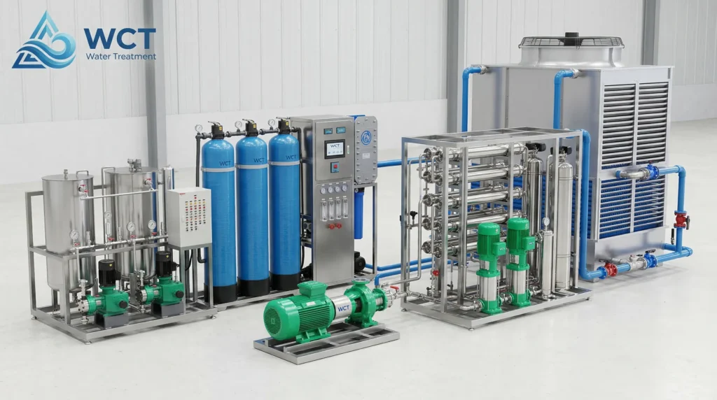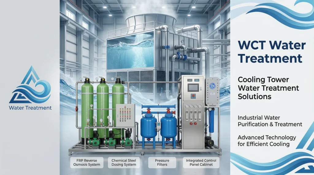
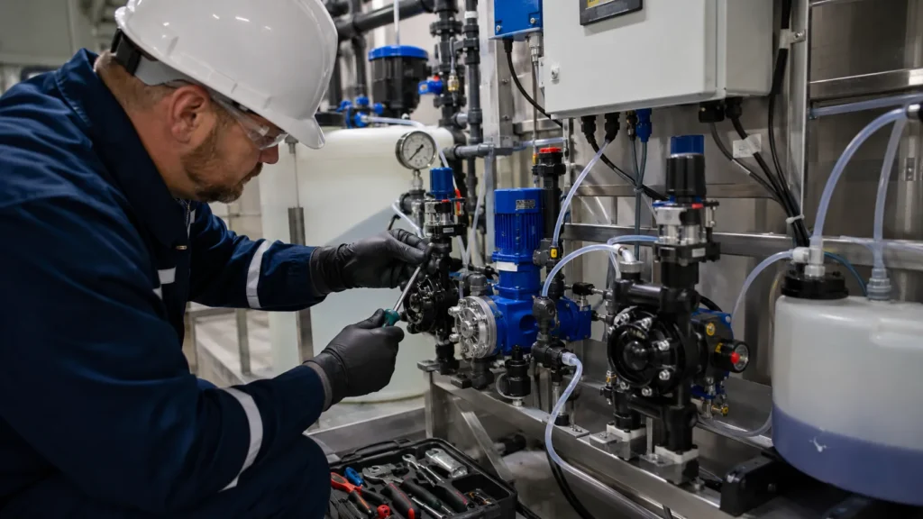
When a dosing skid loses accuracy, it doesn’t just drift out of spec — it can trigger a plant shutdown, release a hazardous chemical, or fail a compliance audit. Effective chemical dosing system maintenance means treating the entire injection loop as one interdependent system: calibration columns, pulsation dampeners, back pressure valves, and wetted parts all interact with the chemical injection skid and the aggressive reagent inside it. This guide provides an SOP-grade approach to maintaining that complete assembly, not just the pump.
Safety and Preparation: The Neutralization Protocol
Before opening any wetted part, isolate the system and flush it with a neutralizing fluid matched to the process chemical. Skipping this step is the single largest cause of chemical burns and unexpected exothermic reactions during maintenance.
- Lock-out/Tag-out (LOTO): Disconnect power to the dosing pump motor and lock out the breaker. Confirm zero energy state at the pump. Never rely on the control system alone.
- PPE requirement: Chemical-resistant gloves (butyl or neoprene, depending on the reagent), face shield, and splash apron must be worn. For ammonia or strong acids, add a full-face respirator if ventilation is limited.
- Residual pressure relief: Open the vent on the calibration column and slowly loosen the discharge-line bleed valve. Trapped pressure in a mechanical diaphragm metering pump head can spray chemical even after the pump stops.
- Neutralization flush: Circulate a neutralizing agent — for example, sodium bicarbonate solution for acids, or a dilute acetic acid solution for caustic — through the pump head and lines. Flush until pH strips show neutral in the rinse water. Drain the system completely before disassembly.
Neutralizing agents must be compatible with pump wetted parts. Verify the IOM manual protocols for the specific chemical before starting any flush. Never use plain water as the first flush for concentrated acids or alkalis; the exothermic reaction can damage seals or cause splattering.
Preventive Maintenance Schedule for Dosing Skids
A tiered maintenance schedule reduces unscheduled downtime and extends diaphragm and valve life. The table below outlines daily, weekly, monthly, and annual tasks that apply to most industrial dosing skids handling water treatment chemicals.
| Frequency | Maintenance Task | Verification Point |
|---|---|---|
| Daily | Check for leaks at fittings, pump head, and valve connections | No visible moisture or crystallization around seals |
| Daily | Verify flow rate against set point via calibration column draw-down timing | Actual flow within ±5% of target L/hr |
| Weekly | Inspect suction strainer and clean if debris is visible | No pressure drop or steam-like vapor in suction line |
| Weekly | Check pulsation dampener charge pressure (if gas-charged) | Pressure matches manufacturer’s pre-charge specification |
| Monthly | Clean suction strainer thoroughly and flush injection check valve seat | Valve ball moves freely, no scale buildup |
| Monthly | Inspect diaphragm for cracking, swelling, or chemical attack | No visible bulging through the tell-tale port |
| Annually | Replace all O-rings, check valve balls, and seals | Material compatibility verified (EPDM vs. Viton vs. PTFE) |
| Annually | Full system calibration verification and back pressure valve cleaning | Back pressure set point within design range; no hunting |
Actual maintenance intervals will vary with chemical aggressiveness and operating hours. Request batch component wear data from the pump manufacturer to fine-tune the schedule for your specific skid.
Component-Specific Care: Diaphragms and Valves
The diaphragm and check valves are the two wetted components most sensitive to the specific chemical being dosed. A routine that works for a polymer skid may fail quickly on a 15% sodium hypochlorite line. Each inspection must target the failure modes that chemical triggers.
Diaphragm Inspection and Fatigue Indicators
Many pump heads include a tell-tale port between the hydraulic and process-side chambers. A visible fluid weep or chemical residue in this port signals a rupture before the chemical reaches the pump housing. Without this indicator, operators rely on pump output drift or erratic suction. When inspecting a diaphragm, look for:
- Surface cracking along the flexing zone
- Swelling or softening that suggests chemical incompatibility
- Permanent deformation that stops the diaphragm from returning to its neutral position
Replace the diaphragm if any of these signs appear, rather than waiting for complete failure. Always verify wetted material compatibility; a diaphragm rated for sodium hypochlorite may fail prematurely in concentrated sulfuric acid service.
Check Valve and Seat Cleaning
Fouled check valves lead to backflow into the calibration column and erratic injection volumes. Remove the valve cartridge and inspect the seat and ball for scale, debris, or chemical buildup. A simple test: the ball should fall freely when the cartridge is tilted. If it sticks, clean with a soft bristle brush and compatible solvent. For severe scaling, replace the valve assembly rather than attempting to scrape the seat, as a damaged seat will never seal correctly.
A frequent oversight is reinstalling an O-ring without lubricating it with the process-compatible grease called for in the IOM manual. Dry O-rings can pinch and create suction-side air leaks.
Step-by-Step Calibration Procedure
Calibration confirms that the pump’s stroke length and speed match the real-world chemical dosage under the system’s piping pressure. A calibration column is the most reliable field method.
- Isolate the supply line: Close the shut-off valve to the chemical day tank and open the calibration column vent so the pump draws only from the column.
- Fill and time: Fill the column with the process chemical. Start the pump and use a stopwatch to measure the time it takes to draw down a known volume, typically 500 or 1000 mL. A 60-second test gives enough data for stable flow rates.
- Calculate flow rate: Convert the draw-down volume to L/hr. Formula:
Flow (L/hr) = (Volume drawn in mL / Time in seconds) × 3.6. Compare this to the set point. - Adjust and repeat: If the rate is off, adjust the stroke length first (for fine trimming) and the motor frequency second (for larger changes). Repeat the draw-down test at least twice more to confirm stability.
For systems where the calibration column is not installed, use a temporary graduated cylinder on the suction side, but be aware that suction height changes affect the actual flow. The addition of a flow rate verification step plus a back pressure valve is recommended for high-precision applications.
System Accessories: Dampeners and Valves
Pulsation dampeners, pressure relief valves, and back pressure valves degrade at different rates depending on the chemical, and neglecting them can silently erode injection accuracy.
Gas-charged pulsation dampeners lose charge pressure over time, which reduces their ability to smooth the discharge flow. Check the pre-charge using a high-resolution pressure gauge monthly and recharge with nitrogen or air per the manufacturer’s spec. A dampener with a ruptured bladder will appear fully charged when checked at rest but will stop smoothing pulsations under flow.
The pressure relief valve (PRV) must be set at least 1–2 bar above the operating discharge pressure to avoid nuisance opening. A PRV that weeps slightly may go unnoticed but will cause continuous chemical loss and a drop in system pressure. Annually, test the set point by raising the pump speed temporarily to confirm the PRV opens at the design value and reseats cleanly.
The back pressure valve (BPV) maintains a steady discharge pressure to prevent siphoning and improve injection rate consistency. Over time, scale or chemical debris can create a partial seat bypass. Clean the BPV during annual maintenance, verify the spring is not corroded, and confirm that the injection check valve at the discharge point opens only when line pressure exceeds the BPV set point. A BPV that sticks open can cause the entire dosing line to drain into the process or allow process pressure feedback into the pump.
Troubleshooting Common Dosing Inaccuracies
Most dosing problems are caused by suction-side restrictions, air entrainment, or worn wetted components — not motor failure. Use the matrix below to isolate the root cause quickly.
| Symptom | Possible Cause | Corrective Action |
|---|---|---|
| No flow | Air lock in pump head | Open prime vent; restart pump with suction line flooded |
| No flow | Clogged suction strainer | Remove and clean strainer; check for chemical coagulation in tank |
| Low flow | Worn diaphragm losing stroke efficiency | Replace diaphragm; check for swelling or cracks |
| Low flow | Fouled discharge check valve | Disassemble and clean valve seat; replace if pitted |
| Erratic flow | Air leak on suction side (fitting or O-ring) | Tighten all suction fittings; replace O-ring if pinched |
| Erratic flow | Back pressure valve hunting | Clean BPV spring and seat; verify system pressure is above BPV minimum |
| Excessive noise | Cavitation due to insufficient suction head | Check NPSH margin; increase suction line diameter or install a charge pump |
| Excessive noise | Loose pulsation dampener bladder | Recharge dampener to correct pressure; if noise persists, replace bladder |
Symptoms like erratic flow can also stem from chemical vapor lock in hot environments. Request a hydraulic performance curve from the pump manufacturer to confirm NPSHr stays within the available suction conditions.
Ensuring Long-Term Reliability: System Audits and Spare Parts
Routine maintenance handled on-site keeps the system running, but annual professional audits identify deeper systemic issues — such as NPSH deficiencies, incorrect wetted parts material selection, or a dampener charge that no longer matches a changed process pressure. An audit can spot trends in diaphragm replacement frequency that indicate chemical compatibility problems long before a leak disrupts operation.
For high-consequence dosing applications, pre-assembled OEM spare parts kits (often called K-kits) reduce downtime by ensuring the right O-rings, valve balls, and diaphragms are on hand. Requesting OEM dosing spare parts rather than aftermarket alternatives maintains pump performance curves and avoids premature part failure. If an audit reveals repeated issues with a particular pump model, our team can recommend an AW series metering pump or a complete chemical dosing system variant better matched to the chemical pair.
Frequently Asked Questions
How often should I replace the pump diaphragm?
Replace the diaphragm between 500 and 1000 operating hours or at the annual service interval, whichever comes first. Aggressive chemicals like concentrated ferric chloride or sodium hypochlorite can shorten diaphragm life to 300 hours; inspection intervals should tighten accordingly.
Why is my dosing pump losing prime frequently?
Frequent loss of prime usually points to a suction-side air leak, a partially clogged suction strainer, or a chemical with high vapor pressure that flashes in the pump head. Check all suction fittings and O-rings first, then verify that the suction line is not restricted and that the chemical temperature stays well below the boiling point at the pump’s suction pressure.
Can I use water to flush a system used for concentrated acid?
Do not use water as the first flush. Adding water to concentrated acids like sulfuric or hydrochloric can cause a violent exothermic reaction, damaging seals and potentially spraying hot acid. Always first flush with a compatible neutralizing agent — typically a weak base solution — then follow with a water rinse only after the neutralization is confirmed.