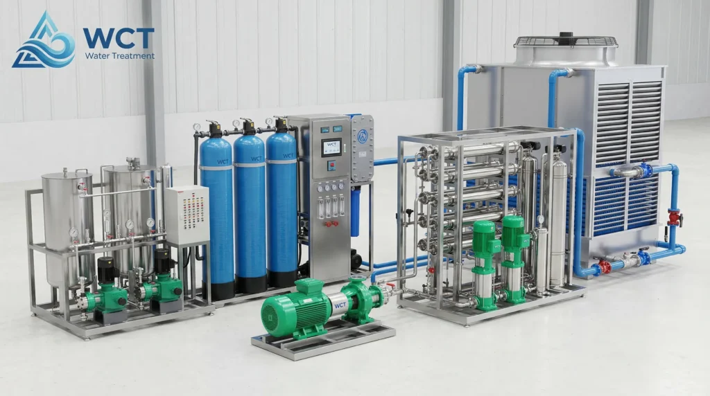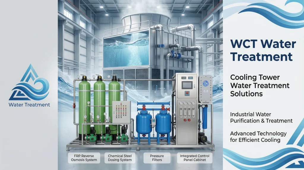
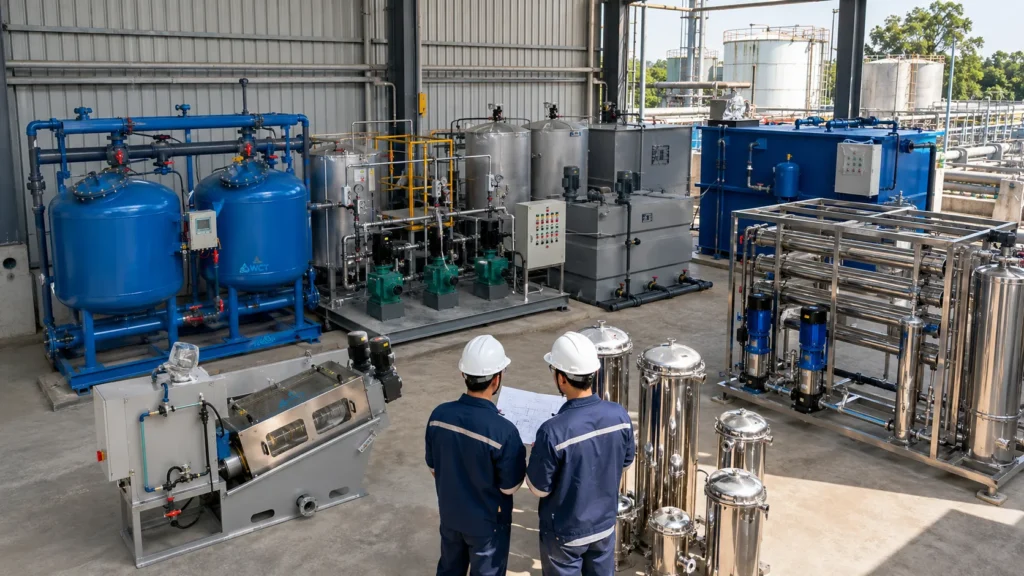
A growing demand spike or tightened discharge permit can turn a six-year custom plant project into an unworkable timeline. For engineers and procurement teams, a packaged water treatment plant shifts the critical path-factory-assembled process modules arrive tested, skid-mounted, and ready for a small site crew to connect utilities and begin commissioning in weeks, not years.
That built-in speed doesn’t eliminate the need for hard technical decisions. Selecting the right treatment modules, sizing the plant for actual peak flows, and preparing a realistic site footprint still determine whether the system meets effluent targets without runaway operating cost.
When to Specify a Pre-Engineered Packaged Plant
A packaged plant earns its place when the alternative is a full-scale field-erected facility with multi-year civil design, lengthy permitting, and high construction risk. The logic is practical: you trade unlimited customization for validated, repeatable performance and a known procurement timeline.
Three conditions typically make the packaged route the right engineering choice.
- Project timelines are compressed by regulatory deadlines or seasonal demand.
- The site has limited set-down area or is remote, making large civil works impractical.
- The treatment train can be assembled from proven unit processes already built inside factory-standard enclosures.
Bypassing custom civil engineering delays
A field-built plant adds months to the schedule just for concrete curing, formwork, and on-site process tie-ins. A packaged plant, by contrast, is pre-assembled on a steel skid with pre-wired instrumentation and pre-piped chemical feeds. Civil work reduces to a simple slab, perimeter drainage, and influent/effluent connections.
We see municipalities cut six to eight months from the front-end schedule when they compare a packaged modular water treatment system to conventional concrete basin construction. That timeline compression often covers regulatory consent decree windows that a stick-built plant would miss.
Skid-mounted configurations for limited footprints
Many industrial plants and small communities do not have acres of spare land. Skid-mounted systems stack multiple treatment stages vertically or within a single containerized envelope, reducing the plant’s set-down area by 40-60 percent compared to sprawling concrete layouts.
The footprint advantage is not just about square footage. It delivers secondary cost savings:
- Reduced site grading and earthwork
- Less subsurface drainage infrastructure
- Shorter interconnecting pipe runs
These savings can add up to 15-25 percent of the total installed budget when evaluating the civil scope holistically.
Factory testing vs. field-built uncertainty
A packaged plant is wet-tested and functionally checked before it leaves the factory floor. The instruments, air scour blowers, media depths, and chemical dosing pumps are already commissioned under controlled conditions.
Field-built plants shift that integration risk to the construction site, where weather, subcontractor coordination, and on-site troubleshooting inflate startup timelines.
That factory testing difference alone is a primary reason integrators and engineering firms increasingly favor pre-engineered modular designs. The benefits of skid-mounted systems extend beyond speed; they reduce start-up process risk that often causes 30-60 day delays in field-built projects.
Treatment Technologies: Matching Process to Source Water
No single packaged plant technology solves every water matrix. The process selection must start with a full influent characterization: turbidity, TSS, BOD, ammonia, and any industrial-specific contaminants like heavy metals or fats-oils-grease. The right process train keeps effluent consistently within permit limits while minimizing operator attention.
The table below groups the most common packaged treatment technologies by capability, footprint intensity, and ideal application.
| Technology | Best For | Advantages | Footprint Intensity |
|---|---|---|---|
| MBR (Membrane Bioreactor) | Strict reuse or tight discharge, high-strength organic wastewater | Clarifier-quality effluent from a small envelope; retains biomass, high resilience to load swings | Low to medium |
| SBR (Sequencing Batch Reactor) | Municipal and low-to-medium industrial flows with variable load | Simple basin-and-blower design; no separate clarifier; tolerant of intermittent operation | Medium |
| MBBR (Moving Bed Biofilm Reactor) | Medium-to-high flows with limited operator availability | Self-regulating biomass on carriers; minimal sludge handling; compact structured media | Low |
| Mixed Media Filtration | Surface water, groundwater, or tertiary polishing after biological treatment | Multi-layer depth filtration; removes fine solids and particulate iron/manganese reliably | Very low |
| Enhanced Clarification + Tube Settling | High-turbidity surface water or industrial pre-treatment | Rapid settling in a small footprint; often front-end of a multi-barrier train | Low |
This technology map matters because many plants combine stages: an SBR or MBBR for biological bulk removal, followed by mixed media filtration or MBR membranes for polishing. Understanding where one process hands off to the next is the difference between hitting effluent targets and chasing persistent permit excursions.
Biological Treatment: MBR vs. SBR vs. MBBR
For wastewater applications, biological package plants dominate. The decision between an MBR package plant, SBR, and MBBR usually comes down to effluent quality requirements and available manpower.
- MBR (Membrane Bioreactor): Produces the highest-quality effluent-typically < 5 mg/L TSS and < 3 NTU turbidity-making it the go-to for water reuse or ultra-sensitive discharge. However, it carries higher membrane cleaning and air-scour energy costs.
- SBR (Sequencing Batch Reactor): Reduces capital outlay and is forgiving if flows are intermittent, but needs disciplined decant and sludge-wasting sequences.
- MBBR (Moving Bed Biofilm Reactor): Lands in the middle: robust, operator-light, and expandable by simply adding media carriers. However, it won’t achieve the same low turbidity as MBR without downstream polishing.
Clarification and Mixed Media Filtration
When influent is surface water or groundwater rather than raw sewage, clarification combined with mixed media filtration often forms the core of a packaged potable or process water plant. The process follows this sequence:
- Chemical coagulant-alum or ferric chloride-destabilizes colloidal particles.
- Tube settlers accelerate particle separation.
- A multi-layer filter of anthracite, sand, and garnet removes the remaining floc.
This physical-chemical approach eliminates the biomass management complexity of biological systems and reaches potable turbidity levels (0.1-0.3 NTU) when designed correctly. Industrial process water users frequently prefer this route to avoid introducing bacteria into closed-loop cooling or boiler feed systems.
Multi-Barrier Protection for Difficult Source Water
Some source waters-highly variable surface supplies, industrial process water with unpredictable contaminants-require more than one treatment barrier. A packaged plant that integrates chemical conditioning, enhanced clarification, and mixed media filtration in a single train provides multi-barrier protection against turbidity spikes, seasonal algae blooms, and occasional heavy metal excursions.
We recommend this approach when source water turbidity swings exceed 50 NTU from dry to wet season, or when an industrial site cannot risk any single-process failure reaching the final outfall. Each barrier acts as a failsafe for the one upstream.
Plant Sizing, GPD Capacity, and Footprint Constraints
Getting GPD capacity right is not a matter of taking annual average flow and adding an arbitrary safety factor.
A plant sized purely on average daily flow will fail during peak wet weather or shift-change dumps, washing out biomass or pushing solids past filters. The design must handle peak sustained rates while leaving headroom for equalization.
The footprint determination then flows directly from the chosen process and capacity. The table below provides realistic space envelopes for common packaged plant capacities, assuming a skid-mounted or containerized layout.
| Flow Range (GPD) | Typical Footprint (L x W, ft) | Typical Skid Count | Common Application |
|---|---|---|---|
| 10,000 – 50,000 | 20 x 40 – 30 x 60 | 1-2 skids | Small subdivision, remote camp, resort |
| 100,000 – 500,000 | 40 x 80 – 60 x 120 | 2-4 skids | Small municipality, large industrial park |
| 500,000 – 2,000,000 | 60 x 140 – 100 x 200 | 4-8 skids | Regional municipal plant, large industrial complex |
These footprints assume basic slab and access clearance. Add about 15 percent more area for chemical storage, electrical MCC enclosures, and operator walkways. Blower and pump noise attenuation enclosures may also require additional setback in noise-sensitive locations.
Calculating peak vs. average daily flow
Mistakes start when buyers submit the facility’s average daily flow to a supplier without disclosing the peak hourly factor.
A small town’s average might be 80,000 GPD, but the morning peak can exceed 3.5 times the average for two hours. The packaged plant’s hydraulic profile must accommodate that surge without short-circuiting biological zones or exceeding clarifier rise rates.
A safe design basis follows two rules:
- Size the biological treatment volume on average daily flow.
- Size the equalization tank and final separation step on peak hourly flow.
If no flow data logger information is available, request at least six weeks of detailed flow monitoring before finalizing the skid configuration.
The mistake: Underestimating equalization needs
Skipping or undersizing an equalization tank is the most common cause of early performance failure in packaged plants. Industrial batch dumps, school lunchtime flows, or stormwater infiltration can spike hydraulic and organic loads beyond what the biological zone can treat.
An equalization tank sized for 20-30 percent of daily flow (with aeration mixing) smooths those peaks, protects downstream membranes, and often reduces required biological volume by preventing washout. The capital cost of a simple equalization tank is far lower than retrofitting an overloaded plant a year after startup.
Application Configurations: Industrial vs. Municipal Requirements
While the mechanical components overlap, the treatment objectives and typical discharge permits differ sharply between municipal and industrial buyers. Packaging a plant for one scenario when it’s intended for the other leads to a mismatch that compliance testing will quickly expose.
Industrial users often need removal of specific metals, emulsified oils, or high-temperature effluent; municipal customers need stable biological nutrient removal and disinfection for public health protection. A skid-mounted systems integrator with experience across both sectors can help translate the application into the right module sequence.
Decentralized municipal and housing development systems
Small municipalities and private developments often cannot afford a centralized plant. A decentralized package plant serving a few hundred to a few thousand homes provides treatment at the point of need, reducing collection system cost and lift station complexity.
These municipal water treatment applications prioritize simple operation, low sludge production, and proven biological processes that meet EPA secondary treatment standards (30 mg/L BOD, 30 mg/L TSS). Where surface discharge is restricted, MBR or tertiary filtration add the polishing needed for irrigation reuse or groundwater recharge.
Industrial process water and effluent compliance
Industrial packaged plants face a different challenge: highly variable loads, often with chemical shock inputs. A food processing plant may discharge four times the design BOD on a cleanup shift; a metal finishing plant needs consistently low heavy metal residuals.
The right industrial process water treatment package often combines multiple stages:
- Physical-chemical pre-treatment: coagulation, pH adjustment, dissolved air flotation.
- Biological polishing: MBBR or MBR.
Factory pre-piping of chemical feeds ensures the dosing points are correctly sequenced, reducing operator error. Effluent compliance is not just about passing a spot sample-it’s about surviving the worst production day each month without an excursion.
Site Preparation and Deployment Timeline
A packaged plant’s “plug-and-play” label refers to the process equipment, not the site. Without proper preparation, the commissioning timeline stretches, and the factory testing advantage erodes. The buyer must have the site pad, utility connections, and access road ready before the skids arrive.
Taking a methodical approach to site readiness before the shipper loads the modules turns a six-week site installation into a two-week connection and test-out window.
Foundation and structural pad requirements
A reinforced concrete slab, typically 12-18 inches thick with perimeter frost protection, forms the base for most packaged plants. Key foundation requirements include:
- Slab must handle the full wet weight of treatment modules-often 150-200% of dry shipped weight.
- Soil bearing capacity confirmed to meet at least 2,500 psf.
- Pad elevation set above the 100-year floodplain or local drainage invert.
For lighter containerized units, a compacted gravel pad with precast concrete footings can suffice, but the vendor’s anchor-bolt layout and point-load drawings must be followed exactly. Omitting a single anchor point or placing it off-layout can void the skid warranty and delay installation.
Electrical and utility tie-ins
While the manufacturer handles internal wiring to a main disconnect, the buyer must provide:
- A dedicated power drop sized for all installed motor loads plus 20% spare capacity for future expansion modules.
- Mitigation for inrush current of air blowers or membrane air scour compressors.
- Voltage drop evaluation on long cable runs from main switchgear to prevent blower motor trips.
Other tie-ins include the influent force main, effluent discharge piping, potable water line for chemical make-up, and a fiber-optic or cellular connection for the SCADA remote monitoring package. Identifying these points early and stubbing them at the slab edge reduces field cutting and rework.
Documents and Specs to Prepare Before Requesting a Quote
Submitting a well-prepared data package to suppliers shortens the quoting cycle and improves the accuracy of the technical proposal. Without it, you’re likely to receive a one-size-fits-all budget estimate that won’t hold up during detailed engineering.
Gather these items before you contact a package plant manufacturer or integrator.
- Average and peak daily flow (GPD), with diurnal flow pattern if available.
- Complete influent water quality: BOD, TSS, ammonia, total nitrogen, total phosphorus, pH, temperature range, and any industrial-specific parameters (oil & grease, heavy metals).
- Target effluent standards-regulatory permit limits for BOD, TSS, nutrients, and coliform or turbidity for reuse.
- Available site footprint (length x width) and any height restrictions.
- Power supply details: voltage, phase, available fault current, and distance from source to pad.
- Anticipated operator skill level and desired automation degree.
Supplying this data allows our application engineering team to quickly narrow the technology choice, right-size the treatment train, and produce a configuration-specific schematic. It also flags early where equalization or pre-treatment is needed before biological stages, avoiding costly project scope changes later.
Chemical dosing in packaged plants can be optimized for O&M cost reduction once the influent chemistry is known, so including complete water analysis data is particularly valuable.
To initiate a preliminary sizing evaluation: submit your flow and water quality data directly to our engineers. This step typically produces a ballpark GPD capacity confirmation and initial skid layout within two weeks.
Frequently Asked Questions About Packaged Treatment Plants
Are packaged water treatment plants permanent or temporary?
They are designed for permanent installation with a 20- to 30-year operational life. However, skid-mounted configurations can be relocated if the site’s needs change, and many suppliers offer lease-to-own or temporary mobile unit options for construction-phase or emergency capacity. The structural steel and corrosion-resistant coatings are specified for continuous outdoor operation across that lifespan.
How many homes can a decentralized packaged wastewater plant serve?
A safe planning figure is 350-400 gallons per day per household including infiltration. So a 100,000 GPD plant typically serves 250-285 homes, depending on local water use patterns. For municipal equivalents, add allowances for schools, small commercial areas, and a safety margin of about 15 percent for wet-weather inflow.
What is the typical lead time for a pre-engineered plant?
Standard packaged plant delivery ranges from 12 to 20 weeks for most 100,000-500,000 GPD configurations, from approved submittals to factory acceptance testing. Large or highly customized units with complex controls can extend to 24 weeks. This compares with 12-18 months for a comparable field-erected plant, assuming no construction delays.