Clarifiers and separators rarely enter a plant as a solo decision. They arrive inside a bigger question: how do we modernize the treatment train to keep discharge limits, handle a changing waste stream, and avoid retrofits that overpromise on footprint or maintenance load.
This guide unpacks the equipment boundary that trips up many facility teams and supplies the selection logic to route the right physical separation step into yours.
Core Mechanical Distinctions in Industrial Separation
The most practical starting point is the phase boundary. Clarifiers and separators handle different separation physics, and swapping the equipment because a quote looks cheaper usually leads to a permit deviation or a maintenance headache within the first quarter.
A clarifier is designed to settle suspended solids out of a liquid phase. A separator splits two liquid phases-most commonly oil and water-and will often remove light solids as a secondary benefit.
Mix up that assignment, and you are either sending solids into a coalescing pack or forcing a gravity settler to deal with an emulsion it cannot touch.
| System Type | Primary Function | Phases Processed | Driving Mechanism | Typical Discharge Result |
|---|---|---|---|---|
| Clarifier | Suspended solids removal | Solid-liquid | Gravity settling (stokes-law zone) | Settled sludge blanket plus clarified overflow |
| Separator | Liquid-liquid division | Liquid-liquid (with possible light solids) | Specific gravity differential, often assisted by coalescing media or centrifugal force | Separated oil/organic phase, separated water phase, occasional sludge |
Clarifier Systems: Gravity Settling for Suspended Solids
Clarifiers reduce total suspended solids by creating a low-velocity hydraulic zone where heavy particulates can fall into a sludge collection zone. This is the workhorse step that keeps TSS from overloading downstream filtration or biological treatment.
The real site decision is rarely whether to clarify, but which stage the clarifier serves and how much space you can give it. Two configuration choices drive the equipment layout and its footprint.
Primary vs. Secondary Clarification
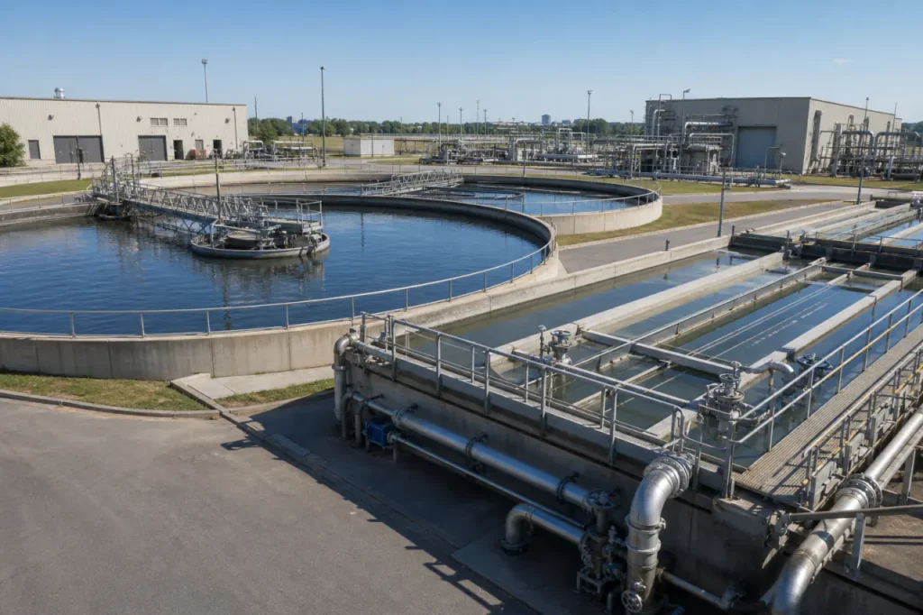
In a municipal or industrial treatment plant, circular clarifiers typically serve two distinct roles because solids settle differently at each point.
Primary clarification removes raw settleable solids before biological treatment, while secondary clarification captures the lighter biological floc that follows.
The design requirements for each stage differ in ways that affect equipment sizing and effluent quality.
- Primary sludge: Dense, gritty, and fairly predictable. Hydraulic retention times are shorter, and the clarifier can handle higher surface loading rates.
- Secondary sludge: Light biological floc that is prone to bulking. It demands a longer HRT and careful hydraulic design to avoid solids carryover that would violate discharge permits.
Inclined Plate (Lamella) Configurations
Inclined plate clarifiers (lamella settlers) multiply effective settling area by stacking plates at an angle, reducing the footprint to a fraction of a circular basin. They are a strong candidate when space is tight or modular expansion is planned.
Lamella performance depends heavily on the characteristics of the influent solids. Several factors tip the decision toward or away from inclined plates:
- Footprint savings: Lamella units typically need 2-4 times less surface area than an equivalent circular clarifier, which can avoid civil construction costs.
- Sensitivity to solids surges: A sudden TSS spike can blind the plate pack if the inlet distribution isn’t designed to handle the variance. Equalization or coarse screening upstream reduces this risk.
- Consistent loading fit: Lamella settlers work best for streams with steady solids characteristics. Plants with batch dumps or highly variable concentrations need careful hydraulic buffering.
- Modular installation: Multiple units can be added in parallel for capacity expansion without a shutdown, keeping the plant online during growth.
Separator Systems: Dividing Liquid Phases and Emulsions
Liquid-liquid separators rely on density difference. The lighter phase-usually oil, fuel, or a chemical solvent-rises while the heavier water phase sinks.
The equipment’s job is to create a calm separation zone, collect each phase, and prevent remixing.
Oil-water separator systems are the most common industrial example, but the same physics apply to many two-phase chemical streams.
When the density differential is small or the oil droplets are tiny, passive separation alone is too slow. That is where the next two mechanisms come in.
Coalescing Oil-Water Separators
Coalescing media forces fine oil droplets to merge into larger buoyant masses that rise quickly. A corrugated or oleophilic plate pack gives the oil a surface to attach to, cutting the required rise distance and improving separation efficiency at higher flow rates.
This approach is well-matched for non-emulsified free oil, but several factors determine whether the media will perform reliably over time:
- Oil type: Works best with free oil that shears into fine droplets but doesn’t form chemically stabilized emulsions. Detergents or surfactants can defeat coalescing by preventing droplet merging.
- Solids management: Grit and heavy solids must be settled out before the coalescing pack; otherwise they pack the media and reduce performance. A sludge collection zone is essential.
- Maintenance access: The media needs periodic cleaning or replacement, especially in high-solids streams. Design should allow easy plate extraction without draining the entire vessel.
Centrifugal Separators and Decanters
When gravity or coalescing cannot deliver the effluent spec, active centrifugal separation force becomes the correct choice. Hydrocyclones and disc-stack centrifuges spin the stream at high velocity, amplifying density differences. This reduces retention time dramatically and can handle emulsified layers that passive units cannot break.
Centrifugal systems bring unique operating conditions that need to be weighed against the separation performance:
- Performance edge: Can split liquids with specific gravity differentials as low as 0.01, and handle stable emulsions that would pass through a standard coalescing pack.
- Energy and maintenance: Higher power consumption and more frequent rotating-part maintenance mean the lifecycle cost is higher than gravity systems.
- Footprint reality: Suitable when space is extremely limited and the discharge limit is legally tight, but the skid weight and vibration must be integrated into the building design.
Application Selection Matrix for Plant Waste Streams
An equipment type will only perform as well as the waste stream it is matched to.
The matrix below is the quick selection shortcut we use when a facility first sends over flow data and waste characterization.
It groups typical industrial streams against the system type that generates a reliable discharge.
| Waste Stream Type | Recommended System | Key Technology | Process Goal |
|---|---|---|---|
| Heavy particulate runoff (mining, aggregate, concrete cutting) | Clarifier (circular or lamella) | Gravity settling / inclined plate | Remove settleable solids before discharge or reuse |
| Non-emulsified oily wash water (vehicle bays, parts washing) | Oil-water separator with coalescing | Coalescing media, gravity separation | Separate free oil and light solids to meet sewer or reuse limits |
| Biological sludge (municipal WWTP, food processing activated sludge) | Secondary clarifier | Gravity settling with scraper | Capture biological floc, return activated sludge, clarify effluent |
| Mixed-phase industrial effluent (refinery interceptor, chemical plant wastewater) | Combined clarifier-separator train or centrifugal unit | Inclined plate + coalescing, or hydrocyclone | Remove settleable solids then split liquid phases for compliance or product recovery |
System Integration Within the Treatment Train
Neither clarifiers nor separators are a standalone treatment plant. Their sequencing matters, and the most expensive mistake is placing a separator where solids loading will bury the coalescing pack within weeks.
These integration patterns show up across most industrial wastewater treatment projects we walk through:
- Pretreatment protection: An oil-water separator placed ahead of a primary clarifier prevents free oil from fouling the scraper mechanism and from interfering with settling. This is critical when the plant also feeds a downstream membrane bioreactor; oil will blind the membranes fast.
- Post-treatment polishing: A secondary clarifier or inclined plate settler after a flocculation step captures the chemically bound solids. This is the standard arrangement to meet suspended solids limits before final filtration or direct effluent discharge.
- Modular capacity expansion: Modular lamella settlers and packaged oil-water separators can be added in parallel when production increases. This avoids a large civil construction project for a new circular basin and keeps the plant online during growth.
- Standalone process loops: In closed-loop wash systems, a small oil-water separator may be the only external treatment step, returning clarified water to the pressure washer while removing free oil and settled grit.
Key Operating Conditions and Process Monitoring
Both clarifiers and separators have a narrow hydraulic comfort zone. Push the flow rate too high, and you lose separation efficiency. Let solids accumulate unmoved, and you eventually see a sludge blanket release that spikes the effluent turbidity.
A few operating parameters deserve continuous attention, especially when the waste stream varies seasonally or with production batches:
- Hydraulic loading rate and retention time: Clarifiers need a surface overflow rate below the particle settling velocity. A sudden flow surge from a washdown event can exceed that and carry solids over the weir. Flow equalization tanks upstream are the most reliable fix.
- Sludge blanket depth monitoring: Sludge-level detectors on the clarifier floor prevent the blanket from rising into the plate pack or weir zone. The setpoint is typically within a few inches of the design blanket height, and a daily check avoids an afternoon non-compliance event.
- Effluent turbidity and oil-in-water monitoring: Continuous turbidity sensors on the clarifier overflow and an oil-in-water analyzer on the separator effluent give operators early warning before a permit sample is collected. This is especially valuable when effluent discharge compliance is legally enforced on a daily composite basis.
- Routine maintenance touchpoints: Scraper drives, weir cleanliness, and coalescing media condition. For inclined plate clarifiers, a periodic visual inspection of the plate pack for solids buildup prevents unexpected performance decline.
Customizing Your Industrial Separation System
Waste Characterization Data Requirements
Properly sizing a clarifier or separator is not a catalog pick. It starts with a full waste characterization. Without accurate data on flow, loading, and phase properties, even a well-built system will underperform. The necessary measurements include:
- Maximum and average flow rate (peak hourly, not just daily average).
- Total suspended solids (TSS) and particle size distribution.
- Oil and grease concentration, and whether the oil is free or emulsified.
- pH and temperature, which affect settling velocities and material compatibility.
- Specific gravity of the target liquid phase to determine separation driving force.
Pilot Testing and Final Design
We recommend a pilot test when the waste composition is variable or contains emulsifying agents that could defeat a standard coalescing setup. The pilot run validates several critical design parameters:
- Hydraulic retention time needed at peak flow to meet discharge limits.
- Actual removal efficiency for the target solids or oil phase.
- Compatibility of plate media or coalescing pack with the waste chemistry (temperature, pH, surfactants).
- Sludge production rate to size the collection zone and removal frequency.
Once the data is in hand, the engineering team sizes the unit for peak hourly flow, not just daily average, and selects the plate spacing, coalescing media grade, or centrifugal system speed that fits the physical properties of the stream.
The deliverable is a treatment module that will fit into the existing pipe rack and control architecture without re-engineering the whole plant.
If you have a recent waste characterization report and a sketch of the available tie-in points, our process group can turn that into a preliminary system layout and a compliance estimate within a few business days.
The next step is a no-obligation technical review of the stream data and site constraints. Contact our engineering team to schedule that review and get a tailored separation module scoped for your facility.