How can industrial facilities cost-effectively manage high-volume concentrate streams while complying with stricter effluent regulations?
Implementing a targeted system for RO reject water treatment allows plant operators to recover additional process water, concentrate dissolved inorganic solids, and dramatically minimize liquid waste volumes before off-site disposal or zero-discharge processing.
The Chemical Profile of RO Reject Water
Primary reverse osmosis (RO) systems typically operate at recovery rates between 75% and 85% on brackish surface or groundwater feeds, and 35% to 50% on high-salinity industrial wastewater streams. The residual volume-known as RO concentrate, reject water, or brine-retains virtually all rejected dissolved species.
As a result, the reject stream exhibits a total dissolved solids (TDS) concentration 3 to 10 times higher than the original feed water.
TDS Concentration and Limiting Salts
Managing RO concentrate requires evaluating the chemical solubility limits of specific sparingly soluble salts rather than looking solely at baseline TDS.
As water is forced through membranes, mineral salts concentrate in the reject channel until they approach or exceed their thermodynamic solubility products (Ksp). Key limiting compounds include:
- Silica (SiO2): Solubility is naturally limited to approximately 120-150 mg/L at neutral pH and ambient temperatures. Exceeding this threshold leads to amorphous silica polymerization, which forms a dense, glass-like scale on membrane surfaces that cannot be removed with standard acid or alkaline chemical washes.
- Calcium Sulfate (CaSO4 / Gypsum): Unlike calcium carbonate, gypsum solubility does not decrease with higher pH, making it a persistent scaling threat in high-recovery membrane stages.
- Barium and Strontium Sulfates (BaSO4 / SrSO4): These salts possess extremely low solubility thresholds. Even microgram-per-liter concentrations in raw water can reach supersaturation in the concentrate channel, causing irreversible membrane precipitation.
- Calcium Carbonate (CaCO3): Strongly dependent on pH and alkalinity. While manageable with acid dosing or antiscalants in primary RO, it becomes aggressive in secondary concentration steps.
Standard spiral-wound polymeric membranes hit physical operating limits around 70,000 to 80,000 mg/L TDS due to feed spacer geometry, flow channel pressure drops, and elevated osmotic pressure requirements.
Pushing recovery beyond these limits without chemical modification or specialized secondary equipment results in rapid flux decline, membrane scaling, and structural element failure.
Regulatory and Disposal Challenges
Historical disposal pathways for RO concentrate are rapidly closing or becoming economically unsustainable for manufacturing facilities. Surface water discharge permits (NPDES) are imposing tighter mass-based limits on total dissolved solids, chlorides, heavy metals, and specific ion species to prevent salinization of freshwater receiving bodies.
Publicly Owned Treatment Works (POTWs) routinely reject industrial concentrate due to pass-through toxicity and interference with biological municipal treatment processes.
Alternative options like deep well injection face stringent local hydrogeological permitting and long-term liability concerns. Off-site commercial liquid waste hauling costs can range from $0.10 to upwards of $0.35 per gallon, converting high-volume brine into a massive operational expense.
Installing dedicated water treatment equipment for industrial use on-site converts brine management from an ongoing waste liability into an operational resource recovery process.
Comparison of RO Reject Treatment Technologies
Selecting the correct technology to process RO concentrate depends on feed water chemistry, volume reduction targets, available footprint, and site energy sources.
Industrial plant owners typically evaluate four primary technology paths, moving from pressure-driven membrane processes to electro-driven separations, and finally to thermal evaporator and crystallizer hardware.
Secondary RO (2-Stage Recovery)
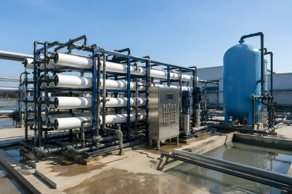
Secondary membrane recovery utilizes high-pressure or disk-tube reverse osmosis (DTRO) configurations to extract additional permeate from the primary reject stream.
Because feed water entering this stage is already near saturation, secondary RO relies heavily on chemical softening pretreatment (such as lime-soda softening or weak acid cation exchange) or specialized high-efficiency antiscalants to prevent scale formation.
Operating pressures often range from 70 bar to 120 bar (1,000 to 1,700 psi), pushing the maximum brine concentration to roughly 80,000-100,000 mg/L TDS.
Electrodialysis and EDR
Electrodialysis Reversal (EDR) uses direct electric current to pull dissolved cations and anions through alternating cation-exchange and anion-exchange membranes. Unlike pressure-driven RO, water does not pass through the membranes; instead, ions migrate out of the feed stream into a concentrated brine stream.
EDR systems regularly reverse the electrical polarity across the cell stack. This reversal changes the direction of ion movement, breaking up micro-precipitates and flushing early-stage scale off membrane surfaces without shutting down operation.
EDR effectively treats high-silica reject streams up to approximately 100,000-120,000 mg/L TDS where traditional polymeric RO membranes experience severe fouling.
Thermal Evaporators
When concentrate TDS exceeds membrane operational thresholds (above 100,000 mg/L), thermal processes become necessary. Mechanical Vapor Recompression (MVR) evaporators compress overhead water vapor to elevate its enthalpy, using the latent heat of condensation to boil incoming reject water.
MVR evaporators concentrate brine up to approximately 250,000-300,000 mg/L TDS, reducing liquid waste volume by 80% to 90% compared to the secondary reject feed.
Comparing an industrial water recycling comparison shows that thermal evaporators require higher initial capital investment but drastically diminish off-site disposal expenses.
Brine Crystallizers
Crystallizers represent the final thermal step when liquid discharge must be completely eliminated.
Operating as forced-circulation steam-heated units, crystallizers drive remaining moisture out of saturated brine slurry until salts precipitate out of solution as solid crystals.
Dewatering equipment then isolates the solid cake, leaving zero residual liquid stream.
| Technology | Operating TDS Limit (mg/L) | Typical Water Recovery (%) | Physical Footprint Profile |
|---|---|---|---|
| Secondary RO (2-Stage) | 70,000 – 90,000 | 40% – 60% (of primary reject) | Compact skid-mounted design |
| Electrodialysis Reversal (EDR) | 80,000 – 120,000 | 50% – 75% (of primary reject) | Moderate; membrane stack arrays |
| MVR Thermal Evaporators | 250,000 – 300,000 | 80% – 92% (of secondary concentrate) | Large vertical footprint; vessel towers |
| Brine Crystallizers | 300,000+ (To dryness) | 95% – 99%+ (Total water recovery) | Large footprint; includes dewatering gear |
Achieving Zero Liquid Discharge (ZLD) for RO Concentrate
Zero Liquid Discharge (ZLD) eliminates liquid waste streams from industrial sites entirely, converting all dissolved contaminants into dry, manageable solid salts while returning purified water back to facility operations.
Achieving ZLD exclusively through thermal evaporation is capital-intensive; therefore, modern process architecture uses a multi-stage hybrid approach to minimize thermal energy demand.
The ZLD Process Architecture
A standard high-efficiency ZLD train integrates membrane pre-concentration ahead of thermal hardware to minimize the volumetric feed rate to the evaporators:
- Primary RO System: Processes raw process water or wastewater, producing high-purity permeate (75%-85% yield) and leaving a high-TDS reject stream.
- Chemical Pretreatment & Softening: Secondary reject is treated with soda ash, caustic soda, or lime, combined with clarifiers or media filtration to strip out hardness (calcium, magnesium) and silica.
- Secondary Membrane Concentration: A secondary high-pressure RO or EDR stack further concentrates softened water, capturing an additional 50%-70% water recovery and reducing liquid volumes heading to thermal processing by more than half.
- Thermal Brine Concentrator (MVR Evaporator): Thermal evaporation processes the concentrated brine, elevating TDS up to slurry thresholds near 300,000 mg/L. Distillate is recovered as pure process water.
- Brine Crystallizer & Dewatering: The concentrated slurry enters a crystallizer. Dewatering machinery, such as a chamber filter press or centrifuge, separates wet solids from mother liquor, yielding dry salt cake.
Integrating an automated ZLD wastewater treatment system ensures that facilities capture maximum water recovery while insulating their operation from changing local environmental discharge regulations.
Managing Solid Waste Byproducts
The solid cake produced by crystallizers contains mixed inorganic salts (primarily sodium chloride, sodium sulfate, and calcium compounds). Plants must handle this byproduct in accordance with local solid waste regulations:
- Mixed Salt Landfilling: Most facilities send mixed crystallizer salt cake to non-hazardous commercial landfills. Moisture content must be reduced below standard paint-filter thresholds before disposal.
- Fractional Crystallization (Resource Recovery): Selective chemical precipitation and multi-stage crystallization can split mixed brine into commercial-grade sodium sulfate or refined sodium chloride, converting waste cake into a salable industrial byproduct.
- Hazardous Waste Classification: If raw RO feed contains heavy metals, complex organic compounds, or toxic minerals, crystallizer cake may classify as hazardous waste, requiring specialized landfill disposal and elevated handling precautions.
Operational Criteria for Technology Selection
Evaluating treatment pathways requires balancing high upfront capital expenditure (CAPEX) against ongoing operating expenses (OPEX). Thermal systems carry high initial equipment costs and significant utility demands, while membrane-based secondary systems trade lower equipment costs for higher chemical consumption and ongoing membrane replacement risks.
Energy Consumption Profiles
Energy represents the primary OPEX driver in concentrate treatment. Membrane operations consume electrical energy to drive booster pumps, whereas thermal processes demand significant thermal or electrical energy for phase changes:
- Secondary High-Pressure RO: Draws 3.0 to 10.0 kWh per cubic meter of treated water, depending on feed osmotic pressure and operating pressure targets.
- Electrodialysis Reversal (EDR): Consumes 4.0 to 12.0 kWh/m³, scaling directly with feed salinity and the mass of ions removed rather than total water volume.
- MVR Evaporators: Utilize highly efficient vapor compressors, averaging 20 to 50 kWh/m³ of evaporated water without requiring continuous steam generation.
- Steam Evaporators / Crystallizers: Require 400 to 700 kWh/m³ equivalent thermal energy if driven by low-pressure steam, or 60 to 100 kWh/m³ electrical energy when utilizing MVR crystallizer configurations.
Designing energy-efficient water treatment systems involves maximizing pre-concentration in membrane stages to ensure thermal equipment handles the absolute smallest volume possible.
Chemical Pre-treatment and Maintenance
Membrane technologies require intense chemical conditioning when handling saturated reject streams. Interstage softening, scale inhibitor dosing, and frequent Clean-In-Place (CIP) cycles using acid and chelating agents add to continuous OPEX.
Conversely, thermal evaporators require anti-foaming agents, caustic pH adjustments, and periodic mechanical or chemical descaling of heat exchanger tubes, particularly when treating high-silica feeds.
| Technology | Relative CAPEX | Relative OPEX | Primary Energy Demand |
|---|---|---|---|
| Secondary RO | Low – Moderate | Moderate (Membranes & Chemicals) | Electrical (High-pressure pumps) |
| Electrodialysis Reversal (EDR) | Moderate | Moderate (Stack maintenance & Power) | Electrical (DC Current stack drive) |
| MVR Thermal Evaporator | High | Moderate – High (Power intensive) | Electrical (Vapor compressor drives) |
| Brine Crystallizer | Very High | High (Thermal or power intensive) | Steam or High-kWh Electrical |
What to Prepare for a System Pilot and Technical Analysis
Engineering an optimal system for RO concentrate recovery requires accurate baseline water quality data. Facilities should avoid sizing treatment trains off single-point water samples, as seasonal surface water changes, raw water blend shifts, and upstream process variations drastically alter concentrate scaling behavior.
Before initiating pilot testing or finalizing system specifications for industrial water treatment equipment, assemble the following site data:
- 30-Day Comprehensive Water Chemistry: Complete analytical testing for TDS, pH, temperature, conductivity, silica (reactive and colloidal), hardness (calcium, magnesium), alkalinity, iron, manganese, sulfate, chloride, and total organic carbon (TOC).
- Volumetric Flow Profiles: Average daily flow rate, peak flow surges, and minimum operational discharge rates expressed in cubic meters per hour or gallons per minute.
- Available Utility Infrastructure: Detailed limits on site power supply (voltage/amps), available low-pressure waste steam, boiler capacity, chilled water, and compressed air availability.
- Target Performance Criteria: Clear definition of required water recovery percentages, maximum allowable discharge TDS, or total Zero Liquid Discharge mandates.
- Physical Site Constraints: Available floor area, ceiling heights, pad loading capacities, and access routes for skid delivery and crane positioning.
During vendor evaluation, treat these as verification checks rather than optional questions:
- Pilot documentation: Ask whether the proposed train has been demonstrated on a similar RO concentrate chemistry. Request pilot performance data including flux decline and cleaning frequency.
- Warranty boundaries: Clarify which chemical pretreatment conditions or TDS limits are excluded from membrane warranty coverage.
- Energy basis: Require utility consumption estimates based on peak feed salinity and seasonal temperature, not annual averages.
- Solids management: Confirm who owns final mixed-salt disposal responsibility and whether the supplier can provide a disposal characterization plan.
Reviewing comprehensive process data enables application specialists at WCT to model scaling tendencies, conduct bench-scale pilot runs, and configure the most cost-effective hybrid treatment train for your facility. Contact our environmental engineering team to evaluate your water analysis and model your RO reject treatment system.
Frequently Asked Questions
Can I route RO reject water directly back into the primary RO system?
Directly recycling RO reject water back into the primary RO feed stream without intermediate treatment is strongly discouraged.
Because the reject water is already saturated with concentrated minerals, blending it into the feed rapidly increases overall feed TDS and pushes sparingly soluble salts past their saturation points.
This practice causes near-instant membrane scaling, severely reduces permeate production, and degrades permeate quality.
Secondary recovery requires intermediate softening, chemical conditioning, or dedicated high-pressure/EDR membrane steps before permeate can be safely extracted.
How does silica affect RO reject evaporation?
High silica concentrations pose a major operational threat to thermal evaporators. As water evaporates, silica concentrates beyond its solubility limit (~120-150 mg/L at neutral pH), precipitating as tough amorphous silica scale on heat exchanger tubes and compressor surfaces.
This scale severely impedes thermal transfer and requires difficult mechanical removal or hazardous hydrofluoric acid washes.
To prevent silica scaling in thermal equipment, facilities operating an industrial water treatment process typically utilize chemical desilication, maintain high pH levels (above 10.5) in the evaporator to increase silica solubility, or install crystallizer seed-slurry technology to promote controlled precipitation in solution rather than on metal surfaces.