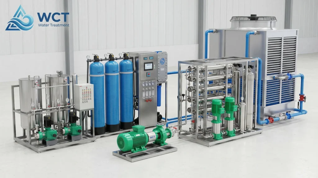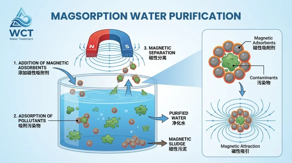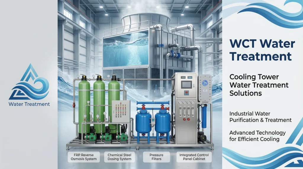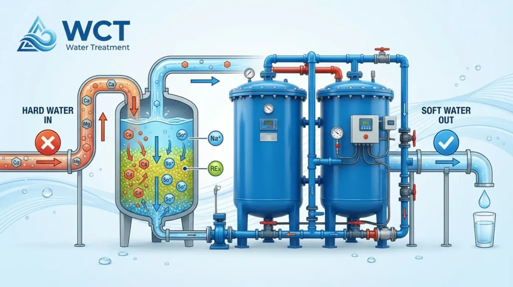
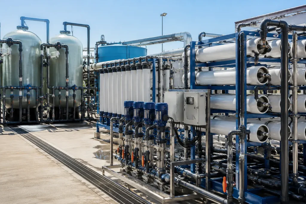
Premature membrane failure in industrial reverse osmosis facilities is rarely caused by manufacturing defects; in over 80% of operating sites, the root cause is an improperly specified RO pretreatment system.
When raw feedwater quality shifts without adequate upstream protection, severe foulants cause membrane flux to drop, inflating operating pressure, increasing clean-in-place (CIP) frequency, and shortening element lifespan.
The Operational Risk of Inadequate Feedwater Pretreatment
An optimized pretreatment train extends membrane life by 3 to 5 years while keeping high-pressure energy requirements near baseline design levels.
Industrial reverse osmosis (RO) membranes use thin-film composite polyamide layers with pores smaller than 0.001 microns. These membranes are exceptionally sensitive to physical, chemical, and biological contaminants present in raw water.
Unfiltered feed streams introduce distinct failure mechanisms that directly affect plant uptime:
- Particulate and Colloidal Fouling: Suspended silt, clay, and inorganic colloids accumulate on the active membrane surface and inside feed spacer channels. Measuring total suspended solids measurement and Silt Density Index (SDI) allows engineers to calculate fouling velocity; an SDI15 greater than 5.0 typically causes rapid element plugging.
- Mineral Scaling: As purified water passes through the membrane barrier, dissolved minerals concentrate in the reject stream. When ions like calcium, magnesium, barium, and silicate exceed saturation thresholds, calcium carbonate scaling and sulfate precipitates form hard mineral scale directly on the membrane polymer.
- Chemical Oxidation: Polyamide RO membranes cannot tolerate continuous exposure to free halogens. Unneutralized residual chlorine or chlorine dioxide breaks down the nitrogen-hydrogen bonds in the polyamide structure, causing irreversible rejection loss and elevated permeate salinity.
- Biological Biofouling: Bacteria and algae adhere to feed spacers and produce extracellular polymeric substances (EPS). This gel-like biofilm traps circulating debris, increases system differential pressure, and requires aggressive, chemical-intensive clean-in-place (CIP) frequency to clean.
Contaminant-to-Pretreatment Technology Matrix
Selecting the correct pretreatment equipment requires matching target foulants from a detailed water chemistry analysis to their corresponding unit operations. No single technology removes every class of impurity, making targeted process selection essential.
| Raw Water Contaminant | Primary Foulant Risk | Recommended Pretreatment Technology | Process Function |
|---|---|---|---|
| Hardness (Ca²⁺, Mg²⁺), Sulfates | Mineral Scaling (CaCO₃, CaSO₄) | Softening Resins or Antiscalant Dosing | Exchanges hard ions or inhibits crystal growth mechanisms |
| Free Chlorine, Hypochlorite | Polyamide Oxidation Damage | Sodium Bisulfite (SMBS) or Activated Carbon | Chemically reduces free oxidants or removes via catalytic adsorption |
| High TSS, Turbidity, Silt | Particulate Plugging, High SDI | multimedia filtration (MMF) systems or Ultrafiltration | Filters particulates down to sub-micron or micro-range limits |
| Dissolved Organics (TOC, Color) | Organic / Biological Biofouling | Organics Scavenger Resins or Coagulation + DAF | Adsorbs or precipitates complex organic molecules before filtration |
| Dissolved Iron (Fe²⁺) and Manganese | Metal Oxide Precipitation | Oxidation (Aeration/Chlorination) + Greensand Filter | Oxidizes soluble metals into insoluble precipitates for media capture |
Contaminants often interact in complex ways. For example, dissolved iron and manganese must be removed upstream before water hits chemical softening resins or membrane systems.
Soluble iron oxidation on a membrane surface can act as an inorganic binder, locking biological matter and particulate silt into a stubborn compound scale layer.
Core Pretreatment Filtration Technologies (Macro to Micro)
Physical filtration serves as the primary barrier for reducing particulate load, lowering raw feedwater turbidity, and maintaining the Silt Density Index within acceptable operating limits (typically SDI15 < 3.0).
Multimedia Filtration (MMF) vs. Ultrafiltration (UF)
Selecting between conventional deep-bed media filtration and advanced membrane filtration depends on source water variability, plant footprint, and required filtrate quality.
| Technology | Nominal Micron Rating | SDI Reduction Capability | Capital Cost Profile | Typical Recovery Rate |
|---|---|---|---|---|
| Multimedia Filtration (MMF) | 10 – 25 microns | Reduces SDI to 3.0 – 5.0 | Lower initial capital expenditure | 90 – 95% (net after backwash) |
| Microfiltration (MF) | 0.1 – 0.2 microns | Reduces SDI to 2.0 – 3.0 | Moderate capital expenditure | 93 – 96% |
| Ultrafiltration (UF) | 0.01 – 0.02 microns | Consistently achieves SDI < 2.0 | Higher initial capital expenditure | 95 – 98% |
While multimedia filters remain cost-effective for stable groundwater sources with low suspended solids, surface water feeds with seasonal turbidity spikes or algae blooms often exceed MMF capabilities.
Modern industrial designs increasingly favor ultrafiltration (UF) pretreatment.
UF modules provide an absolute physical barrier that removes suspended solids, colloidal silica, and microorganisms regardless of inlet feed spikes, providing a consistent feed quality to downstream RO membranes.
Cartridge and Bag Filtration (The Final Barrier)
Cartridge filter housings positioned immediately ahead of high-pressure RO pumps act as non-cleansing safety traps.
Equipped with 1-micron to 5-micron spun polypropylene or pleated depth cartridges, these cartridge precision filters capture fugitive media fines, pump wear debris, or flocs that bypass upstream filtration stages.
They are not intended as primary turbidity filters; rapid differential pressure buildup across cartridge elements indicates an operating issue in the primary filtration train.
Chemical Conditioning and Dosing Systems
Physical filtration removes undissolved solids, but chemical conditioning is required to modify dissolved water chemistry and neutralize chemical compounds that pass through mechanical strainers.
Antiscalant and Dispersant Dosing
Antiscalant chemicals interrupt mineral scale formation through threshold inhibition, crystal distortion, and dispersion mechanisms.
Dosing concentrated antiscalants allows the system to operate at elevated recovery rates without exceeding precipitation points for calcium carbonate, calcium sulfate, or silica. Precision metering skid units maintain exact target concentrations.
Over-dosing antiscalant must be avoided, as excess organic polymers can act as a nutrient source for bacteria, promoting biofouling inside the membrane elements.
Dechlorination via Sodium Bisulfite (SMBS)
If upstream chlorine or sodium hypochlorite is added for biofouling control or iron oxidation, residual oxidants must be completely neutralized before reaching polyamide membranes.
SMBS injection units dose sodium bisulfite into the feed line to reduce free chlorine into harmless chloride ions through a rapid stoichiometric reaction:
Na₂S₂O₅ + 2 HOCl + H₂O → 2 NaHSO₄ + 2 HCl
Oxidation-Reduction Potential (ORP) sensors combined with inline pH monitoring provide real-time feedback to control dosing pump speeds, keeping feed ORP levels below +300 mV. Granular activated carbon (GAC) beds offer a non-chemical dechlorination alternative, though carbon beds can harbour bacterial growth if not systematically sanitized.
Coagulation and Flocculation (For highly turbid surface water)
Surface water containing fine colloidal clays and organic humic acids often resists direct filtration. Injecting inorganic coagulants (such as ferric chloride or polyaluminum chloride) neutralizes negative particle charges.
This allows microscopic suspended solids to bind into larger flocs that can be effectively filtered by MMF units or dissolved air flotation (DAF) systems.
Process Train Architecture: Designing for Specific Feedwater
An RO pretreatment system should be engineered based on the specific raw water source. A design suited for city tap water will quickly fail if applied to surface water or seawater desalination plants.
Municipal Tap Water Architecture
City water feeds generally feature low turbidity and consistent inorganic chemistry, but contain municipal disinfectant residuals.
- Dechlorination Stage: Sodium bisulfite dosing skid (or GAC media bed) to protect polyamide elements from residual free chlorine.
- Hardness / Scaling Control: antiscalant chemical dosing skid to inhibit calcium carbonate scaling during concentration.
- Security Filtration: 5-micron pleated cartridge filter housing to intercept pipe rust and municipal sediment.
- Desalination Stage: High-pressure pump feeding spiral-wound brackish reverse osmosis membranes.
Brackish Surface Water Architecture
Surface waters (rivers, lakes, intake ponds) experience seasonal variation in total suspended solids, organic loading, and biological activity.
- Coagulation / Clarification: In-line chemical coagulation paired with clarification or dissolved air flotation (DAF) to drop heavy TSS and algae.
- Primary Filtration: Automated backwashing multimedia sand filter array or an integrated ultrafiltration module train.
- Chemical Conditioning: SMBS dechlorination dosing alongside specialized silica/hard-water antiscalant injection.
- Polishing Barrier: High-efficiency 1-micron cartridge filters acting as a safety trap prior to reverse osmosis separation.
Seawater Desalination (SWRO) Pretreatment
Seawater exhibits high total dissolved solids (TDS), elevated salinity, corrosion potential, and variable marine biological activity.
- Intake Screening: Coarse and fine mechanical screen filters to capture macro-organisms, seaweed, and debris.
- Pre-Chlorination & Shock Treatment: Controlled biocide injection at intake to minimize macro-fouling in piping networks.
- Membrane Ultrafiltration (UF): High-flux hollow-fiber UF train providing robust SDI reduction (SDI < 2.0) during red-tide biological events.
- Chemical Neutralization & Scale Prevention: Dechlorination via SMBS, target antiscalant addition, and pH adjustment.
- High-Pressure Trap & Desalination: Duplex stainless-steel cartridge housings supplying pressurized water to SWRO membranes and energy recovery devices (ERDs).
What to Prepare Before Custom RO Pretreatment Design
To design an effective RO pretreatment system, application engineers rely on actual site water quality parameters rather than baseline estimates. Before requesting an engineering design or sizing proposal, compile the following operational parameters:
- Complete Water Analysis Report: Lab-certified analysis including cations (Ca²⁺, Mg²⁺, Na⁺, Fe²⁺, Mn²⁺), anions (HCO₃⁻, SO₄²⁻, Cl⁻), dissolved silica, pH, TOC, and turbidity.
- Silt Density Index (SDI₁₅) & TSS: On-site SDI measurements across seasonal operational variations, especially for surface water sources.
- Temperature Range: Minimum, average, and maximum feed water temperatures (temperature directly affects membrane flux rates and net driving pressure).
- Production Targets & Recovery Rate: Required permeate flow rate (m³/hr or GPM) and preferred system recovery targets based on water conservation goals.
- Site Utility & Space Boundaries: Available installation footprint, ceiling clearance, available electrical supply, and local wastewater discharge limits for backwash streams.
Providing accurate water quality data helps ensure the pretreatment system protects downstream assets correctly. To evaluate your raw water analysis and configure a complete pretreatment and reverse osmosis system tailored to your facility, consult with the engineering team at WCT.