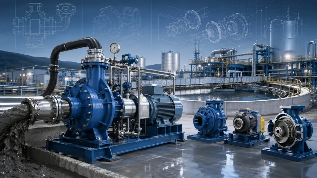
A slurry feed pump mismatch is a reliability risk that can bring an entire process line to a halt. When the pump casing wears through in weeks instead of years because of incorrect metallurgy, or when solids settle inside the suction piping because flow velocity was underestimated, the cost is far more than the repair bill—it is lost production time and heightened safety exposure.
This selection guide addresses the engineering decisions that directly determine pump performance and wear life. We will walk through mechanical design differences, sizing calculations that account for slurry density rather than clear water, material science behind liners and impellers, and the application-specific demands of mining, wastewater, and dredging operations. Each section is written to help you specify the right pump configuration the first time.
Understanding Slurry Feed Pump Mechanics
A slurry feed pump is a specialized centrifugal or positive displacement pump designed to transport abrasive and high-density mixtures of solids and liquids through a process cycle. Unlike a standard water pump, every hydraulic passage and wear component is engineered to resist erosion from particles that can be hard, sharp, and moving at high velocity.
The centrifugal variant relies on rotational energy from an impeller to create discharge pressure. Solids are suspended in the fluid and conveyed by hydraulic conveyancing. As the mixture enters the impeller eye, centrifugal force flings it outward into the volute casing. The impeller vane design is critical: slurry impellers typically have fewer and much thicker vanes than clean-water impellers. This open or semi-open geometry reduces the chance of clogging and allows large particles to pass, while the thicker sections absorb wear before losing structural integrity. Positive displacement designs are less common for general slurry feeding but may be applied when extremely high pressures are required, for instance when feeding a filter press in the final stages of a dewatering cycle.
The cross-sectional flow paths inside the casing are also wider and more rounded. This design minimizes internal recirculation zones where small, sharp particles could accelerate local wear. The trade-off is a slight reduction in hydraulic efficiency compared to water pumps, but in slurry service, durability is the priority. Understanding these mechanical differences sets the foundation for proper sizing and material selection.
Critical Technical Specifications for Pump Sizing
Decision rule: Sizing a slurry feed pump requires calculating friction losses based on the actual slurry density and rheology, not the water carrier alone. The goal is to maintain a flow velocity above the particle settling velocity while staying within the pump’s best efficiency window.
| Pump Configuration | Typical Flow Range (m³/h) | Max Head (m) | Max Solid Size (mm) |
|---|---|---|---|
| Horizontal End-Suction | 10 – 4,000 | 60 – 75 | 50 – 100 |
| Vertical Cantilever/Sump | 5 – 1,500 | 40 – 55 | 25 – 80 |
| Heavy-Duty Submersible | 10 – 2,500 | 30 – 50 | 40 – 80 |
Typical ranges shown. Actual performance depends on impeller diameter, motor speed, and slurry properties. Always verify performance curves with the manufacturer for your specific slurry conditions.
Calculating Total Dynamic Head (TDH) for Slurry
Total dynamic head (TDH) in slurry service involves the static head, friction head, and velocity head components, but the friction head is amplified by the slurry’s specific gravity and the presence of suspended solids. While a water pump TDH calculation starts with water’s density, the slurry pump designer must apply a derating factor from the pump curve that accounts for the increase in apparent viscosity and the energy required to keep solids in suspension. Critical inputs include the solid concentration by volume (Cv), particle size distribution, and the slurry’s specific gravity. A common mistake is to size based solely on water performance curves; this leads to undersized motors and insufficient discharge pressure. For accurate sizing, engineers should request slurry-specific performance curves from the manufacturer that show the head and efficiency correction factors at the expected Cv.
NPSH and Suction Side Requirements
NPSH (Net Positive Suction Head) available must exceed the pump’s NPSH required by a comfortable margin, typically 1.0 to 1.5 meters or more, to suppress cavitation at the impeller eye. With slurry, the risk is compounded because cavitation collapse near the vanes not only pits the metal but also accelerates combined erosion-corrosion wear. The suction piping must be designed to avoid solids settling. This means maintaining a minimum flow velocity—often in the range of 2.0 to 3.0 m/s for fine particles and higher for coarse solids—to keep the mixture homogeneous. Suction lift applications need careful evaluation; any drop in line pressure can pull air out of solution and destabilize the feed. A flooded suction with a positive inlet head is always preferred for abrasive slurries, as it provides consistent hydraulic conditions and protects the pump from intermittent starvation.
Material Science: Liners and Impeller Metallurgy
Technical takeaway: Material selection is the single largest lever for extending pump wear life. The rule of thumb is to match the material to the dominant wear mechanism: high-chrome alloys for coarse, high-impact particles and elastomers for fine, low-energy abrasive or acidic slurries.
| Material | Abrasion Resistance | Corrosion Resistance | Typical Hardness / Durometer | Best Particle Suitability |
|---|---|---|---|---|
| High-Chrome White Iron (HCWCI) | Excellent (high-impact) | Moderate | 600+ Brinell | Coarse ore, rock, >6 mm particles |
| Natural Rubber Liners | Good (fine, wet abrasion) | Excellent against many acids (pH 2–10) | 35–45 Shore A | Fine sand, silt, <6 mm, no sharp edges |
| Polyurethane Elastomer | Good (cutting wear from fine solids) | Good (organic chemicals, oils) | 70–95 Shore A | Fine tailings, slimes, some chemical slurries |
| Duplex Stainless Steel | Moderate | Excellent (chloride, acidic) | 250–300 Brinell | Corrosive slurries with moderate abrasion |
Material suitability depends on slurry pH, temperature, particle shape, and impact energy. The table provides general guidance; always confirm compatibility through manufacturer testing.
High-Chrome Alloys vs. Elastomer Liners
High-chrome alloys (25–28% Cr white iron) offer extreme hardness, typically exceeding 600 Brinell, and are the standard for coarse mineral slurries where particle impact is severe. The matrix of hard carbides provides excellent resistance to gouging and high-stress abrasion. However, high-chrome iron is brittle and can be damaged by tramp metal or oversized boulders. Its corrosion resistance to acidic or oxidizing environments is limited. Conversely, elastomer liners like natural rubber absorb impact energy from fine, round particles and are virtually immune to many acidic solutions that would attack metal. The limitation is that elastomers cut and tear when exposed to sharp, angular particles or large solids with high kinetic energy. For applications where both abrasive and corrosive mechanisms are present—such as acidic mine drainage with fine tailings—rubber-lined pumps with stainless steel impellers or duplex materials are often evaluated.
Corrosion-Resistance vs. Abrasion-Resistance
When a slurry is both corrosive and abrasive, the material choice becomes a compromise. Abrasion removes protective surface films, exposing fresh metal to corrosive attack, which in turn softens the surface and accelerates wear. This synergism demands careful alloy or coating selection. For mildly corrosive applications, high-chrome iron with a small addition of molybdenum can improve resistance without sacrificing hardness. When corrosion dominates, 316L or duplex stainless steel wearing parts may be the better choice, even if they wear faster from abrasion than chrome iron. In extreme cases, ceramic-lined components or exotic alloys like CD4MCu are specified. The starting point is always a complete chemical analysis of the carrier liquid, pH, temperature, and oxidation-reduction potential, followed by material selection guidance from the pump manufacturer.
Slurry Feed Pump Types and Configurations
Best-fit scenario framework: Horizontal end-suction pumps are the workhorse choice where accessible floor space and regular maintenance are available. Vertical cantilever pumps eliminate submerged bearings and seals for abrasive sump applications. Submersible designs provide a compact, sealed package for deep, wet installations.
Horizontal End-Suction Pumps
These pumps are the most common configuration for in-plant slurry transfer and process feeding. The casing and impeller are mounted on a horizontal shaft with a bearing housing at the drive end. Maintenance is straightforward because the rotating assembly can be removed without disturbing the suction or discharge piping. The design is well suited for feeding hydrocyclones, thickeners, and flotation cells in mining. Large access covers and replaceable wear liners inside the volute allow for quick wear part replacement. However, horizontal pumps require adequate floor space and a properly designed stuffing box or expeller seal arrangement to protect the shaft from abrasive ingress, especially when the suction pressure fluctuates.
Vertical Cantilever and Sump Pumps
In abrasive sumps, pits, or any application where the pump is submerged but the motor must remain above the liquid level, vertical cantilever designs are preferred. The shaft is suspended from a bearing housing above the sump, and there are no submerged bearings or mechanical seals below the liquid. This eliminates a primary failure point. The impeller is typically a semi-open design that can pass large solids. These pumps are widely used for floor washdown recovery, mill scale removal, and sump drainage. The limitation is that the shaft length must be matched to the sump depth; long shafts require careful dynamic analysis to avoid resonance, and the maximum head is typically lower than that of horizontal pumps because of cantilever stiffness limits.
Heavy-Duty Submersible Slurry Pumps
Where space is constrained or the installation is submerged under variable water levels, such as in deep mine dewatering or construction site dewatering, heavy-duty submersible slurry pumps provide a fully integrated solution. The motor and hydraulic end are sealed inside a watertight casing. Agitators or mechanical stirrers are often built into the pump intake to resuspend settled solids and maintain a consistent feed density. These pumps are designed for high solids handling capacity, with large passageways and wear-resistant impellers. The primary trade-offs are that motor cooling depends entirely on the surrounding fluid, and cable management must be robust enough to survive the abrasive environment. When specifying a submersible, always verify the maximum depth rating and the minimum submergence required to prevent motor overheating.
Application-Specific Selection Criteria
What to verify: Slurry feed pumps are not one-size-fits-all. The required discharge characteristic—steady high pressure at low flow for a filter press versus high-volume flow for a cyclone—determines the pump curve and often the pump type you need.
Mining and Mineral Processing
In mining, slurry feed pumps move dense ore slurries through grinding, classification, and tailings circuits. The emphasis is on abrasion resistance under high-impact conditions. Coarse particles from SAG mills and ball mill discharge demand high-chrome iron impellers and liners. The pump must handle fluctuating solid concentration by volume (Cv), often reaching 40% or more. When feeding hydrocyclones, the pump operates at a high flow rate with moderate head; the feed pressure must be steady to maintain cut point efficiency. For tailings disposal, multiple pumps may be staged to overcome long pipeline friction losses. Always account for the pipe loop pressure drop at the slurry density, not at water density, when sizing these systems.
Wastewater and Manure Management
In municipal and industrial wastewater plants, slurry feed pumps often deal with grit-laden sludge and organic solids. Here, the particles are typically softer but can include stringy material that requires a pump with a large, unobstructed impeller passage. When the pump is feeding sludge dewatering systems such as a screw press dewatering unit or a filter press dewatering cycle, the pump curve must match the changing system resistance: as the press fills, the discharge pressure rises while the flow drops. Progressive cavity pumps are sometimes chosen for this duty, but when a centrifugal slurry pump is specified, it must have a steep enough curve to maintain pressure at reduced flow without operating too far left of BEP. In manure management, corrosive fluids and high fiber content may lead to specifying elastomer liners and a chopper or vortex impeller design to prevent plugging. Our dissolved air flotation systems often receive thickened sludge from such feed pumps.
Dredging and Sand Excavation
Dredging applications involve high volumes of sand, gravel, and silt at relatively low static heads. The pump casing and impeller are typically large and wear-resistant, often with replaceable wear parts. The main challenge is the abrasive power of fast-moving sand particles, which can erode pump internals quickly. Rubber-lined pumps are common in sand dredging where particle size is under about 6 mm and angularity is low. For coarser river gravel, high-chrome iron or even hard metal-overlay impellers are specified. Suction performance is critical; a deep dredge ladder requires a pump with excellent NPSH characteristics, often met by placing the pump as close to the water as possible or using a submerged hydraulic drive.
Optimizing Wear Life and Maintenance Intervals
Maintenance rule: The most effective wear-life strategy is to keep the pump operating as close to its Best Efficiency Point (BEP) as practical. Running too far to the left or right of BEP accelerates recirculation, turbulence, and localized erosion inside the casing.
Impeller front clearance between the impeller vanes and the suction wear plate directly affects hydraulic efficiency and internal recirculation. As wear progresses, this clearance increases, allowing high-velocity slurry to recirculate back to the suction side, which dramatically reduces pump output and increases casing wear. Regularly adjusting the clearance—often via an external adjustment mechanism threaded into the bearing housing or a simple shim arrangement—restores the original performance and reduces wasteful energy consumption. Many operations establish a clearance check interval based on the predicted wear life of the liner material, typically every few hundred operating hours in highly abrasive service.
Seal selection is equally critical. Traditional packed glands with a flush water system can be effective if flush water pressure and flow are maintained above the slurry pressure at the stuffing box. However, expeller seals (dynamic centrifugal seals) are widely preferred for slurry feed pumps because they operate without external flush water and can run completely dry. An expeller uses a secondary impeller behind the main impeller to create a centrifugal force that pushes slurry away from the shaft opening. When combined with a lip seal or a simple gland arrangement, expeller seals dramatically reduce product dilution and water consumption. Mechanical seals, when specified, must be of heavy-duty cartridge design with hard face materials like silicon carbide and tungsten carbide to resist the abrasive environment.
Beyond the pump itself, a feed sump or tank must allow sufficient residence time for solids to remain in suspension despite the pump’s draw. Air entrainment from vortex formation at the suction is a hidden enemy; it causes uneven loading and vibration. Anti-vortex baffles and a well-designed sump floor slope toward the suction pipe are practical measures that extend pump life.
Consult an Application Engineer for Custom Slurry Solutions
Reliability factor: Slurry characteristics vary not just between sites but between different process stages on the same site. The only way to eliminate guesswork in material selection and performance prediction is to work from a slurry sample analysis and a full system curve review.
General selection guidelines and tables provide a starting point, but particle angularity, the presence of fines that form a viscous dense medium, corrosive agents, and temperature swings all shift the optimal material and hydraulic envelope. We recommend submitting a representative slurry sample for lab analysis, along with your process flow diagram and desired operating point. Our application engineers use these inputs to model the system curve with slurry-specific friction loss correction and to select the impeller material, liner compound, and seal configuration that deliver the longest documented mean time between failures.
When standard alloy and elastomer options are not enough, custom-engineered liners with variable thickness in high-wear zones, oversized impeller passages, and unique vane geometries can be developed. Whether you need a single pump for a difficult feed application or a full set of dewatering filter press feed pumps with matching control systems, we can provide performance curves and a commercial proposal based on your data. Contact our technical team with your duty conditions and we will start the sizing analysis the same week.
Frequently Asked Questions
What is the difference between a slurry pump and a sludge pump?
Slurry refers to a mixture of liquid and hard, abrasive solids such as ore, sand, or rock. A slurry pump is built with hardened wear components to handle this abrasion. Sludge typically contains softer, often organic solids or settled waste; sludge pumps may prioritize clog-free passage and chemical compatibility over extreme abrasion resistance. In practice, many wastewater sludge handling applications can use either type depending on the grit load.
How does slurry density affect motor horsepower requirements?
Higher slurry density, characterized by specific gravity and solid concentration, directly increases the power demand. The absorbed power is proportional to the product of flow, head, and specific gravity. If a pump is sized on water performance curves, the motor will be severely overloaded when the same pump handles a slurry with a specific gravity of 1.5 or higher. Always size the motor based on the maximum expected slurry density, not the average.
Why is my slurry pump wearing out prematurely?
The most common reasons are operating too far from the Best Efficiency Point (BEP), which induces destructive recirculation and off-design velocity patterns, and material selection mismatched to the particle size, shape, or slurry chemistry. Undersized suction piping, resulting in air entrainment and cavitation, also accelerates wear. Review your pump’s operating point against its published curve and verify that the liner and impeller material are correct for your particle analysis.
Can a slurry pump run dry?
Centrifugal slurry pumps with mechanical seals or packed glands should never run dry, as seal faces depend on the pumped fluid for cooling and lubrication. Vertical cantilever pumps that use an expeller seal and have no submerged bearings are somewhat more tolerant of interrupted flow, but even they risk overheating if run dry for more than a few seconds. Always ensure a flooded suction or reliable priming system.