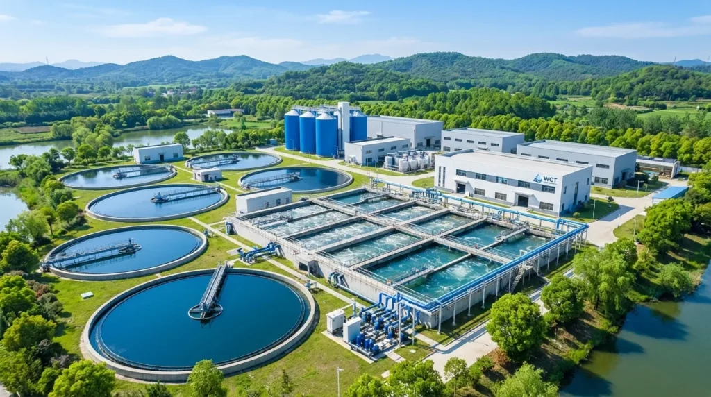
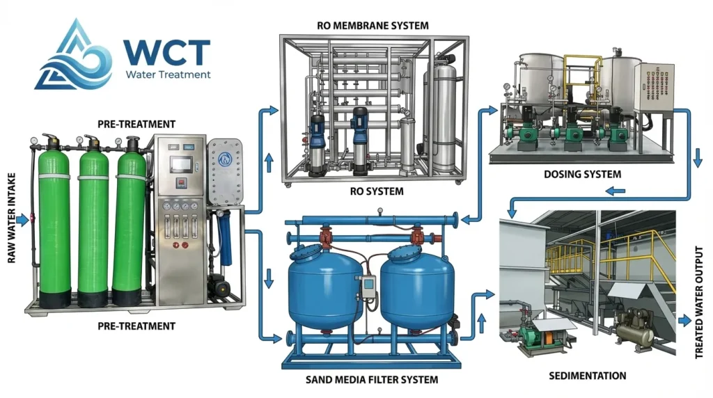
Phase 1: Preliminary Treatment & Intake (The Headworks)
The foundation of any effective process flow diagram for a water treatment plant begins at the headworks. This initial phase is critical because it dictates the hydraulic profile for the entire facility. Whether we are drawing from a deep well, a river intake, or handling raw industrial effluent, the primary goal here is stabilization and protection.
Raw Water Intake and Screening
The process starts with the raw water intake. Before we even consider chemical treatment or filtration, we must physically remove large debris that could damage sensitive downstream equipment.
- Intake: Water is drawn from the source, often containing variable loads of suspended solids.
- Screening & Grit Removal: Large solids—sticks, plastics, and coarse grit—are mechanically screened out. This step is non-negotiable; failing to remove these abrasive materials will inevitably lead to clogged valves and eroded impellers later in the flow.
WCT Integration: Establishing Hydraulic Pressure
Once the large debris is cleared, the water must be moved efficiently to the primary treatment units. This is where pump selection becomes a decisive factor in the plant\’s operational success.
At WCT, we integrate CDLF+CDH High-Pressure Pumps directly into this phase. In a robust process flow, these pumps serve as the heartbeat of the intake system.
- Consistent Flow: They ensure a steady hydraulic load, preventing surges that can disrupt settling tanks or overwhelm chemical dosing units.
- Durability: Built to handle rigorous industrial demands, these pumps maintain the necessary head pressure to drive water through the initial piping network without fluctuation.
By securing a reliable intake mechanism with high-performance pumping, we protect the integrity of the entire downstream process.
Phase 2: Chemical Conditioning & Coagulation
In any comprehensive process flow diagram water treatment plant, physical separation alone is rarely enough. While screens handle large debris, microscopic suspended solids and colloids require a shift from mechanics to chemistry. This phase is critical for destabilizing particles so they can clump together and be removed downstream.
Flash Mixing and Coagulant Injection
On the P&ID (Piping and Instrumentation Diagram), this is the stage where \”Flash Mixing\” occurs. We introduce coagulants—typically Polyaluminum Chloride (PAC) or Polyacrylamide (PAM)—directly into the turbulent flow. The objective is rapid, uniform dispersion to neutralize the electrical charges on particles, preparing them for flocculation.
Precision Dosing Equipment
To maintain the integrity of the process flow, we utilize our specialized Automatic Powder/Liquid Dosing Systems. Reliability here is non-negotiable, which is why we integrate specific high-performance components:
- AXB Series Mechanical Diaphragm Metering Pumps: These pumps provide consistent hydraulic pressure, ensuring the exact volume of chemical is injected regardless of system backpressure.
- PE304 Stainless Steel Tanks: Durability matters. We utilize PE304 stainless steel chemical dosing tanks to resist corrosion from aggressive chemicals, offering a significant upgrade over standard plastic vessels.
Why Precision Matters
Accuracy in this phase directly impacts operational costs and regulatory compliance. Over-dosing wastes expensive chemicals and increases sludge volume, while under-dosing results in poor water quality that fails to meet discharge standards. Our engineered chemical dosing systems automate this delicate balance, ensuring the chemical feed matches the real-time requirements of the incoming water load.
Phase 3: Solid-Liquid Separation and Clarification
In any effective process flow diagram water treatment plant layout, this phase is where the visible separation occurs. Once the chemicals have done their job, we need to physically remove the contaminants. The choice of equipment here depends entirely on physics: specifically, the density of the pollutants relative to water.
Sedimentation vs. Flotation
We generally categorize this stage into two distinct paths on the flow chart:
- Sedimentation: Used when pollutants are heavier than water (like grit, mud, or heavy metal precipitates). Gravity pulls them to the bottom.
- Flotation: Used when pollutants are lighter than water or neutrally buoyant (like oils, grease, algae, or fine fibers). We need to help these float to the surface.
Flocculation Basins
Before entering the main separation tanks, the water typically moves through flocculation basins. This is where the small, destabilized particles created in the previous chemical phase collide and clump together into larger \”flocs.\” Larger flocs settle or float much faster, making the downstream equipment far more efficient.
WCT Separation Solutions
At WCT, we tailor the equipment to the specific wastewater profile:
- For Light Solids & Oils: We deploy Dissolved Air Flotation (DAF) systems. On your process diagram, this appears as a tank where millions of micro-bubbles attach to suspended solids, lifting them to the surface where a skimmer removes the sludge layer. This is critical for industrial applications where oil and grease are present.
- For Heavy Sludge: We utilize Sedimentation Tanks for standard gravity settling. To optimize space and efficiency, we often enhance these tanks with honeycomb inclined tube packing, which significantly increases the effective settling area without increasing the tank\’s footprint. On the diagram, this is represented as a large basin with a conical bottom or a scraper mechanism that directs settled sludge to a bottom outlet.
Phase 4: Advanced Filtration and Polishing in the Process Flow Diagram
Once the water has passed through initial clarification, the process flow diagram water treatment plant moves into the critical stage of advanced filtration. This phase is where we transition from simply removing visible solids to eliminating microscopic contaminants and dissolved impurities to achieve high-purity standards.
Media Filtration: The First Line of Defense
Before reaching sensitive membrane systems, the water must undergo media filtration. In our designs, we typically integrate sand or carbon filters at this stage to trap residual suspended solids that may have escaped the sedimentation or flotation tanks. This step is vital for reducing the turbidity of the water and protecting downstream equipment from fouling. For many sewage applications, a robust WCT sand media filter is the standard choice for reliable particulate removal.
Precision Filtration and Membrane Protection
You cannot feed water directly from a sand filter into a Reverse Osmosis (RO) unit without risking damage. The flow diagram must include a safety barrier. We utilize Precision Filters as a mandatory pre-treatment step. These units capture fine particles that could clog or scratch delicate membrane surfaces. By installing a high-quality WCT precision filter, we ensure that the feed water meets the strict Silt Density Index (SDI) requirements needed for membrane longevity.
RO Systems and Desalination
The heart of this phase is the Reverse Osmosis (RO) System. This is where the heavy lifting happens for chemical purification.
- Standard RO Systems: For industrial recycling or zero discharge projects, our RO units remove dissolved salts, heavy metals, and bacteria, producing water suitable for reuse or safe discharge.
- Seawater Desalination: For coastal clients, the process flow adapts to handle high salinity. We deploy specialized small seawater desalination systems designed to withstand the corrosive nature of ocean water while delivering potable output.
By strictly adhering to this multi-barrier approach—Media Filter ➔ Precision Filter ➔ RO System—we guarantee that the final water quality meets the specific demands of your industry.
Phase 5: Disinfection & Sludge Management
In the final stages of a process flow diagram water treatment plant, the stream splits into two distinct paths: the polished effluent and the residual solids. This phase is critical for ensuring regulatory compliance and minimizing waste disposal costs.
Final Effluent Disinfection
Before the water leaves the plant for reuse or discharge, it must pass through a disinfection stage to neutralize any remaining biological contaminants. Depending on the specific application—whether it is for industrial reuse or safe environmental discharge—we typically integrate injection points for:
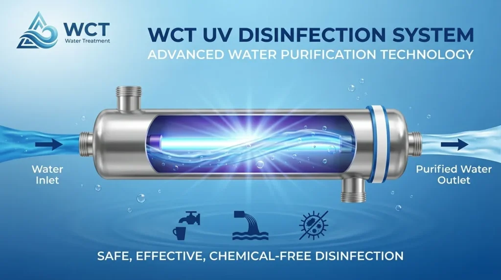
- UV Sterilization: For chemical-free pathogen neutralization.
- Chlorine or Ozone: For residual disinfection power in distribution lines.
The Sludge Handling Loop
The \”bottom\” section of the process flow diagram is dedicated to the solids removed during earlier clarification stages. Managing this waste efficiently is often where operational costs can spike if not engineered correctly.
At WCT, we focus on volume reduction to lower transport and disposal fees. Our approach involves two key pieces of equipment:
- Polymer Dosing Units: Raw sludge is often too watery to press directly. We utilize precise chemical dosing to inject polymers that condition the sludge, causing solids to flocculate and separate more easily from the water.
- Sludge Dewatering Equipment: Once conditioned, the sludge enters our dewatering systems. This equipment mechanically squeezes out the remaining liquid, turning liquid slurry into a dry, manageable cake.
For many projects, especially those with limited space, our integrated sewage treatment equipment streamlines this entire solids handling process into a compact, efficient footprint. Properly mapping this loop on your diagram ensures you account for the filtrate return—the dirty water squeezed from the sludge—which must be sent back to the headworks for re-treatment.
Customizing the Flow: Modular vs. Industrial Scale
A process flow diagram water treatment plant is never a one-size-fits-all document. The complexity of the flow changes drastically depending on whether you are treating domestic sewage in a small community or managing high-salinity effluent in a large industrial facility.
For Domestic Sewage, the flow is typically linear and biological. It focuses on removing organics and pathogens efficiently. However, when we design for Industrial Zero Liquid Discharge (ZLD), the diagram becomes a complex loop. We have to account for recycling every drop of water, which introduces additional steps like evaporation and crystallization into the PFD.
This is where WCT’s engineering strength comes into play. With 12 years of experience and a team of 20+ R&D engineers, we don\’t just sell parts; we engineer the entire flow. We hold 30 patents (including 20 core and 10 invention patents) that allow us to optimize these diagrams for specific needs.
- Skid-Mounted Units: For clients with limited space or remote sites, we condense the entire PFD into compact, containerized systems. These are \”plug-and-play\” solutions where the piping and instrumentation are pre-assembled.
- Civil Construction Layouts: For large-scale municipal or heavy industrial projects, we design expansive flows that integrate seamlessly with on-site civil works.
Whether you need a compact industrial water treatment skid or a sprawling facility layout, our team customizes the process flow to match your exact operational footprint and regulatory requirements.
Why Component Quality Matters in Your Process Flow
A process flow diagram water treatment plant relies on might look flawless on paper, but a drawing doesn\’t have to deal with corrosion, high pressure, or 24/7 operation. In the real world, the theoretical flow is only as good as the physical equipment supporting it. If a single valve leaks or a pump fails, that perfect diagram becomes a costly shutdown.
We prioritize durability because we know industrial environments are unforgiving. That is why we use materials like PE304 stainless steel for our chemical dosing tanks instead of cheaper plastics that degrade over time. It is also why we engineer robust components like the WCT AXB Series Mechanical Diaphragm Metering Pump, ensuring consistent performance even under heavy loads. Our ISO9001 certification serves as a guarantee that your system isn\’t just a concept—it is a reliable, engineered reality that won\’t be interrupted by preventable mechanical failures.