You might already know that a precise water treatment plant diagram is the blueprint for a compliant, high-performing facility…
But how do you translate that paper schematic into real-world, operational equipment?
Well, you\’re in the right place because I\’ve put together a complete breakdown.
As an industry expert with over a decade of experience manufacturing industrial systems at WCT, I know that properly mapping out your industrial water treatment layout is crucial for preventing operational bottlenecks and ensuring environmental compliance.
I\’m going to give you guidance that goes way beyond basic textbook charts—this is actionable advice based on real-world engineering and ISO9001-certified manufacturing experience.
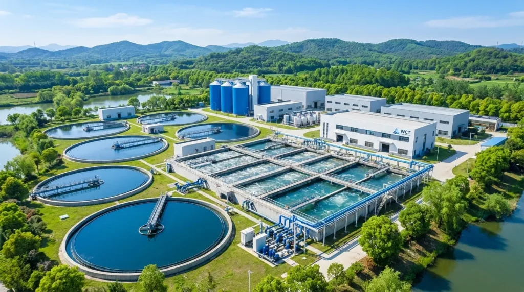
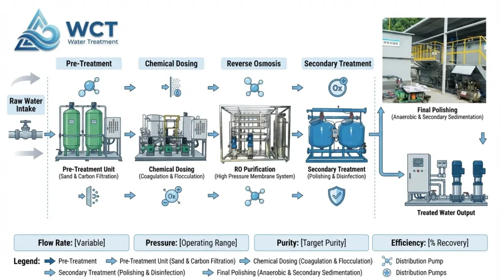
[Image of an industrial water treatment plant process flow diagram]
In this guide, you\’re going to learn exactly how to navigate a complete wastewater treatment process flow, step by step.
From initial chemical dosing to advanced reverse osmosis, I\’ll show you how to match each stage of your water purification schematic with the exact equipment needed to get the job done right.
Let\’s dive right in.
Why Accurate Process Flow Diagrams Matter
Are you dealing with unexpected flow restrictions or struggling to fit new equipment into a tight footprint? For facility engineers and project managers, guessing isn\’t an option. A precise water treatment plant diagram is the fundamental blueprint that turns complex engineering into a streamlined, operational reality.
Preventing Bottlenecks and Guaranteeing Compliance
A well-drafted schematic does more than just show where the pipes go. It actively prevents operational bottlenecks by visualizing the exact sequence of fluid dynamics and chemical interactions. More importantly, it keeps you on the right side of the law. When regulatory bodies review your wastewater treatment process flow, an accurate, logic-driven diagram proves your system is engineered to meet strict environmental discharge limits from day one.
Mapping Spatial Requirements for Heavy Equipment
We know that floor space inside an industrial plant is incredibly expensive. You must map out the exact spatial requirements before pouring a single yard of concrete.
- Large Settling Tanks: These require massive footprints and specific elevations for optimal gravity flow.
- Skid-Mounted Systems: Modular units need precise layout planning to ensure drop-in installation is flawless and maintenance access remains clear.
- Clearance Zones: A detailed diagram water treatment plant layout prevents costly physical clashes between chemical dosing lines, high-pressure pumps, and electrical panels.
Future-Proofing with Smart Water Solutions
Your facility won\’t stay the same size forever. A robust water treatment facility diagram acts as a strategic roadmap for growth. By developing a comprehensive industrial water treatment layout now, you can intentionally allocate space for future expansions. This foresight makes it incredibly easy to scale up capacity or seamlessly integrate smart water solutions—like automated IoT sensors and advanced telemetry—without tearing down your existing infrastructure.
Core Stages of a Standard Water Treatment Plant Diagram
When you look at a comprehensive water treatment plant diagram, the entire purification journey is broken down into distinct, manageable phases. Whether you are dealing with an industrial water treatment layout or standard municipal water purification steps, we rely on these seven core stages to get the job done right.
- Stage 1: Intake and Pre-Treatment
The pre-treatment water phase is where it all begins. We use heavy-duty screening to remove large debris and protect downstream equipment. Durable intake components are critical here during the initial raw water pumping phase to prevent early wear and tear. - Stage 2: Chemical Dosing and Coagulation
To handle microscopic particles, we introduce chemicals that neutralize electrical charges, forcing the particles to bind together. For a reliable chemical dosing equipment setup, we utilize Automatic Chemical Dosing Systems (PAC/PAM). Integrating an automated powder-liquid dosing system alongside our PE304 Stainless Steel dosing tanks ensures precise, corrosion-resistant chemical delivery day in and day out. - Stage 3: Flocculation and Solid-Liquid Separation
Following the coagulation and flocculation process, gentle mixing helps those bound particles form larger, heavier flocs. We then separate the solids from the water using Dissolved Air Flotation (DAF) machines, shallow air flotation units, or rely on a highly efficient sedimentation tank design to let gravity do the heavy lifting. - Stage 4: Precision Filtration and High-Pressure Pumping
Physical barriers step in next. We use Precision Filters to mechanically remove any remaining suspended solids. To keep the flow steady and powerful, we rely on robust CDLF+CDH High-Pressure Pumps and AXB Series Mechanical Diaphragm Metering Pumps. - Stage 5: Advanced Purification and Reverse Osmosis
Any detailed reverse osmosis plant diagram highlights this crucial step. Through advanced membrane filtration, we strip out dissolved solids, heavy metals, and salts. Depending on the scale and water source, we deploy specialized 1000 GPD RO Systems or compact small seawater RO units. - Stage 6: Disinfection and Distribution
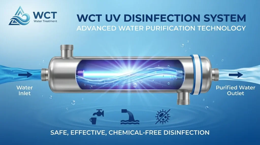
Before the water leaves the facility, it goes through a strict final sterilization phase. We utilize UV, chlorine, or ozone treatments to completely eradicate pathogens and guarantee the water is perfectly safe for final distribution. - Stage 7: Sludge Management and Dewatering
Treating water creates a byproduct of accumulated solids. A proper sludge dewatering process flow is essential for environmental compliance and operational efficiency. We use advanced Sludge Dewatering Systems and Polymer Dosing Units to manage this waste, drastically reducing volume and pushing your facility toward zero discharge.
Customizing the Water Treatment Plant Diagram for Your Industry
No two facilities are exactly alike. While the core stages provide a solid baseline, a practical water treatment plant diagram must shift to match your specific application. What works for a basic municipal setup simply won\’t cut it for complex industrial needs. We always adapt the core schematic based on the exact water source and the required end product.
Domestic Sewage vs. Industrial Layouts
When we design these systems, we see how a standard wastewater treatment process flow completely changes based on the target:
- Domestic Sewage Systems: This setup focuses heavily on biological treatment and reliable clarification. Space is often tight, so the schematic relies on compact, integrated sewage treatment equipment to handle daily organic loads efficiently and safely.
- Industrial Zero-Discharge: An industrial water treatment layout is much more aggressive. The diagram prioritizes advanced chemical dosing, heavy-duty dissolved air flotation systems, and stringent sludge dewatering to ensure absolutely no liquid waste leaves your facility.
Desalination Plant Schematic
Seawater desalination requires its own unique approach. The process flow changes significantly to handle high salinity and highly corrosive environments:
- Upgraded Pre-treatment: Heavy-duty intake screens and specialized anti-corrosive materials are non-negotiable in this water purification schematic.
- High-Pressure Core: The center of the operation revolves around a specialized reverse osmosis plant diagram. It requires specialized small seawater RO units and high-pressure pumping systems built explicitly to force water through membranes, safely stripping away extreme dissolved solids and salts.
Translating Your Water Treatment Plant Diagram into Reality
A perfect water treatment plant diagram on paper is just the starting point. Turning that theoretical water treatment facility layout into a fully operational plant takes real engineering muscle. The gap between a clean schematic and a working system involves complex integrations, strict spatial planning, and precise equipment sizing. A drawing doesn\’t filter water; reliable machinery does.
Built on Proven Engineering
At WCT, we don\’t just hand you a blueprint and walk away. We bring your diagram water treatment plant to life. We bridge the gap between concept and reality with serious industry expertise:
- 20+ R&D Engineers: A dedicated team optimizing your industrial water treatment layout for maximum efficiency.
- 30 Patents: Backed by 20 core and 10 invention patents that drive our proprietary technology forward.
- ISO9001 Certification: Guaranteeing uncompromising quality control across our entire manufacturing process.
A True One-Stop Solution
Piecing together equipment from different vendors based on a generic water treatment diagram is a recipe for operational bottlenecks. We provide a tailored, \”One-Stop\” solution. From the initial design and in-house manufacturing to comprehensive after-sales support, we handle everything under one roof. When you need to develop robust, scalable plants for water treatment, our team ensures your ideal layout translates into a high-performance, compliant, and cost-effective reality.