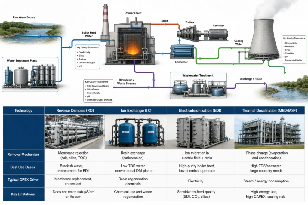
Power plant water treatment prevents the slow drift in heat rate that operations cannot explain for weeks-until silica scaling or condenser fouling forces an outage. Across a plant’s water balance, three streams demand distinct treatment strategies: ultrapure boiler feed and makeup, high-volume cooling tower water, and the wastewater that must meet tightening discharge limits.
The Impact of Water Quality on Power Generation Reliability
Poor water chemistry does not announce itself loudly. It accumulates as silica scale on turbine blades, calcium deposits in condenser tubes, and under-deposit corrosion in boiler drums. Each of these reduces heat transfer efficiency and shortens the interval between forced outages.
A supercritical boiler running on feedwater with conductivity above 0.1 uS/cm will eventually face turbine deposition that erodes capacity and raises maintenance costs. The same logic applies to cooling systems where high cycles of concentration without proper treatment accelerate scaling on condenser surfaces.
Understanding the plant water balance is the first engineering step. Every stream-raw water intake, process condensate return, cooling tower evaporation, blowdown discharge-interacts with the treatment design. Getting one stream wrong usually cascades into the others.
Core Power Plant Applications and Water Quality Requirements
Different plant subsystems do not just need different water quality. They fail in different ways when the quality is wrong. The table below maps the three primary applications to the parameters that typically govern equipment protection and performance.
| Application | Key Quality Parameters | Typical Target Range | Primary Risk if Out of Spec |
|---|---|---|---|
| Boiler Feed (Supercritical) | Conductivity, Silica, TOC | <0.1 uS/cm, <10 ppb SiO2 | Turbine blade deposition, corrosion fatigue |
| Boiler Feed (Subcritical) | Hardness, Silica, Conductivity | <0.3 uS/cm, <20 ppb SiO2 | Boiler tube scaling, caustic gouging |
| Cooling Tower Makeup | Hardness, Alkalinity, Suspended Solids | Varies by cycles of concentration | Condenser scaling, biological fouling |
| Process/Service Water | Suspended Solids, pH, Iron | <5 NTU turbidity | Equipment erosion, nozzle clogging |
Make-Up Water and Boiler Feed Systems
This is the highest-purity stream in the plant. For supercritical units, the boiler feed water treatment train often combines reverse osmosis with electrodeionization or mixed-bed ion exchange to reach the sub-ppb silica levels that turbine manufacturers require.
Make-up water replaces steam cycle losses from blowdown, leaks, and process usage. Its quality directly sets the baseline chemistry for the entire steam-water cycle. Any contaminant introduced here concentrates inside the boiler under high pressure and temperature.
Cooling Tower Operations
Cooling towers consume roughly 70-80% of a thermal plant’s total water intake. Treatment must balance three competing forces: scaling control as water evaporates and leaves minerals behind, corrosion protection for condenser tubes and piping, and biological growth prevention in the warm, wet tower environment.
The cycles of concentration you choose determine how far the makeup water quality can be pushed before blowdown becomes necessary. Higher cycles reduce water consumption but demand tighter chemical control and better cooling tower water treatment.
Process and Service Water
Service water systems need reliable suspended solids removal more than ultrapure chemistry. Ash handling, equipment cooling, and bearing seal water can tolerate some dissolved ions but will fail quickly if particulates clog small-diameter lines or erode pump internals.
The treatment here is usually simpler: screens, multimedia filtration, and sometimes a softener. The mistake plants make is treating service water as an afterthought until a clog forces an unplanned unit derate.
Comparing Treatment Technologies for Demineralization and High-Purity Needs
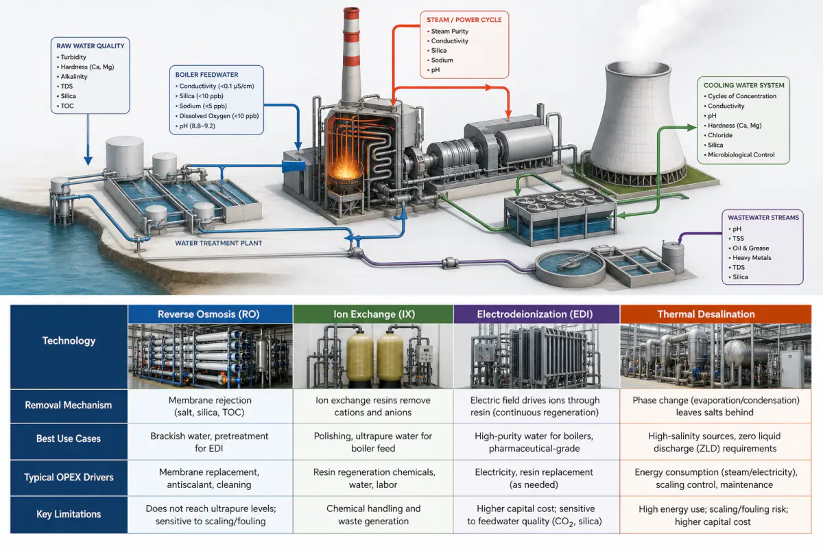
The treatment train you select for demineralization depends on three variables: feedwater salinity, target effluent conductivity, and how much chemical handling your site can support. The table below compares the four most common technologies across operational parameters that drive long-term cost.
| Technology | Removal Mechanism | Best For | Typical OPEX Driver | Key Limitation |
|---|---|---|---|---|
| Reverse Osmosis (RO) | Membrane rejection (salt, silica, TOC) | Brackish water, pretreatment for EDI | Membrane replacement, antiscalant | Does not reach sub-ppb alone |
| Ion Exchange (IX) | Resin bed exchange (cations, anions) | Low-salinity polishing | Regenerant chemicals, resin life | High chemical handling burden |
| Electrodeionization (EDI) | Electric current + membranes | Post-RO polishing, ultrapure water | Module replacement, power | Feed conductivity must be low |
| Thermal (MED/MSF) | Evaporation and condensation | Seawater, ZLD brine concentration | Energy, scaling control | Large footprint, high CAPEX |
Reverse Osmosis (RO) and Membrane Systems
An RO system is the workhorse of modern power plant pretreatment. It removes 97-99% of dissolved salts, silica, and organics in a single step, drastically reducing the ionic load on downstream polishers.
The practical advantage is chemical reduction. A plant that installs RO upstream of its ion exchange beds or EDI modules will cut regenerant chemical consumption by 90% or more. This matters most at sites where acid and caustic handling is operationally expensive or environmentally constrained.
Ion Exchange (IX) and Electrodeionization (EDI)
Ion exchange remains the standard for achieving ultralow conductivity in the final polishing stage. Its weakness is the regeneration cycle, which requires bulk acid and caustic storage and produces a waste brine stream that the plant must manage.
EDI replaces chemical regeneration with electric current, splitting water molecules to continuously regenerate the resin beds. It works best when fed with RO-quality water. For plants targeting the tightest silica and TOC limits without a chemical burden, the RO-EDI train is typically the preferred configuration.
Thermal Desalination and Evaporation
Thermal processes become relevant when feedwater salinity is too high for membrane economics or when the plant is already committed to a ZLD strategy. Multiple-effect distillation (MED) and brine concentrators use steam to evaporate water and leave behind concentrated salts.
The energy cost is high, so thermal treatment rarely makes sense as a standalone demineralization step. It earns its place inside ZLD trains where the alternative is liquid waste disposal with rising regulatory risk.
Cooling Water Treatment and Blowdown Management
Effective cooling water treatment programs keep three problems under control at once: mineral scaling, corrosion, and biological growth. The treatment approach directly affects how many cycles of concentration the tower can run before blowdown becomes necessary.
Chemical Treatment Program Essentials
- Side-stream filtration removes airborne particulates and silt that accumulate in the open cooling loop. A well-designed side-stream filter, sized for 3-5% of total circulation flow, reduces condenser tube fouling and extends chemical program effectiveness.
- Antiscalant and dispersant dosing prevents calcium carbonate, calcium phosphate, and silica from precipitating on heat transfer surfaces as water concentrates.
- Oxidizing biocide programs-chlorine, bromine, or chlorine dioxide-control Legionella risk and prevent biofilm buildup that reduces heat transfer and shelters corrosion cells.
- Online corrosion monitoring on condenser water boxes provides early warning of pH excursions or under-deposit pitting before tube leaks force a unit shutdown.
Blowdown Compliance and Discharge Risks
Blowdown management is where cooling water treatment connects directly to environmental compliance. The blowdown stream carries the concentrated minerals and chemical residuals that the tower rejected.
Discharging it without treatment risks violating NPDES permit limits for temperature, chlorine residual, or metals. A side-stream treatment approach that recovers a portion of blowdown for reuse can reduce both makeup demand and discharge volume.
Wastewater Management and Zero Liquid Discharge (ZLD) Strategies
A zero liquid discharge (ZLD) system eliminates liquid waste streams by recovering reusable water and converting dissolved solids into a solid cake for landfill disposal. For plants facing tight discharge limits or water scarcity, ZLD transforms wastewater from a compliance liability into a water recovery asset.
How a ZLD System Works
The typical process train follows three stages:
- A brine concentrator uses thermal energy to reduce wastewater volume by 90-95%, producing a high-purity distillate and a concentrated brine.
- A crystallizer or spray dryer evaporates the remaining water from the brine, leaving behind crystalline solids.
- A filter press dewaters the solids into a dry cake suitable for landfill disposal.
Waste Streams Suitable for ZLD
The streams that commonly feed a ZLD system include:
- Cooling tower blowdown
- Flue gas desulfurization (FGD) wastewater
- Ion exchange regenerant waste
- RO reject
By recycling this water back to the front of the plant, ZLD can reduce raw water intake by 10-25% depending on the plant’s steam cycle losses and cooling system design.
What Triggers a ZLD Decision
ZLD is capital-intensive, and the operating cost is driven primarily by the energy required for evaporation. The decision to adopt ZLD usually comes from three triggers:
- A regulatory mandate that prohibits liquid discharge
- A water availability constraint at the site
- A corporate sustainability commitment that affects project financing
System Integration and Modular Design Benefits
Modular, skid-mounted treatment systems have replaced stick-built construction for most new power plant water treatment projects. The case for modular design rests on speed, control integration, and future scalability.
Factory-Built Skids for Fast Deployment
Factory assembly and testing reduce field installation time and simplify site layout. Pre-engineered modules arrive ready to connect, cutting weeks from construction schedules and lowering on-site safety risk.
Control Integration with DCS/SCADA
A treatment skid that communicates directly with the DCS or SCADA system allows operators to monitor conductivity, TOC, and flow trends alongside turbine and boiler parameters. This visibility makes it possible to catch chemistry drift before it triggers an alarm.
Automated Chemistry Control
Automated operation reduces manual sampling and chemical adjustments. When the system adjusts antiscalant dosing based on real-time feedwater flow and quality, the plant uses fewer chemicals and runs tighter chemistry control. It also frees operators to focus on the unit, not the water plant.
Built-In Capacity Scalability
A plant that installs a two-train RO-EDI system with space for a third train can add capacity when the unit expands or when cooling tower cycles increase. The upfront cost of the spare skid pad is modest compared with retrofitting a stick-built system later.
Consult a Water Treatment Specialist for System Design
Designing a power plant water treatment train that fits the site’s feedwater chemistry, discharge permit limits, and operating philosophy requires more than a technology comparison table. It starts with a complete water characterization and a plant water balance that accounts for all makeup, condensate return, evaporation, and blowdown flows.
Before you engage an engineering team, assemble the following data: feedwater quality analysis across seasonal variations, target flow rates for each plant subsystem, existing discharge permit limits, and any site constraints on chemical storage or physical footprint.
Having these ready speeds up the feasibility assessment and keeps the discussion grounded in project-specific numbers. We work with utilities and IPPs to develop treatment trains that match the plant’s actual water chemistry and operating profile.
From pilot testing new membrane configurations to designing full-scale ZLD integration, industrial water treatment solutions start with the data and build toward a system that operators can run with confidence.
Reach out to discuss your project’s feedwater report and discharge requirements, and we will provide a technical consultation and process design proposal.